Technical
November / December 2021

Continuous Process: Implementing Low pH Viral Inactivation in a Continuous Process

Kakolie Banerjee
Eric Karl Zimmerer
Joelle Genevieve Johnson
Ushma Mehta
Elizabeth Goodrich
Corinne MIller, PhD
Figure 1: Batch manufacturing process vs. a low pH iVI process.

Viral inactivation (VI) is a critical step in ensuring the safety of monoclonal antibody (mAb), Fc fusion, and recombinant protein therapeutics and it is typically an important component of an overall virus control strategy for downstream biotherapeutic production processes. Considerations for successful implementation of an inline VI process are discussed in this article.

Market drivers have motivated biomanufacturers to set cost reduction and faster production targets while maintaining viral safety and product quality. Transitioning from batch manufacturing to a continuous VI or inline VI (iVI) mode (Figure 1) enables manufacturers to better achieve these targets while providing other advantages, such as a reduced footprint and more streamlined production. Additionally, the smaller equipment facilitates transition to single-use flow paths, which eliminates cleaning and sanitization.

Low pH VI is performed after protein A chromatography to deliver robust inactivation of enveloped viruses. Studies have shown that pH, time, and temperature are critical operating parameters. VI efficacy may also be impacted by protein concentration, isoelectric point (pI), ionic strength, presence of aggregates, buffer systems, and process impurities. The ASTM standard E2888-1 defines conditions that ensure ≥ 5 log reduction value (LRV) of model enveloped rodent retrovirus when a post–protein A eluate is incubated at pH ≤ 3.6 for > 30 minutes.1

Maintaining the feed at target VI conditions for the required duration while under continuous flow is achieved by passing through an incubation chamber. Because the kinetics of VI are rapid, typically achieving > 5 LRV at pH < 3.6 in under 30 minutes,2 ,3 ,4 manufacturers could benefit from shorter exposure times, which would enable the production of pH-sensitive biomolecules without compromising product quality.5  In this article, available incubation chamber designs are presented with a discussion on how industry can adopt these technologies to transition from existing batch processes to iVI.

  • 1ASTM International. ASTM E2888-12. Standard Practice for Process for Inactivation of Rodent Retrovirus by pH. West Conshohocken, PA, ASTM International, 2019. doi:10.1520/E2888-12R19
  • 2Gillespie, C., M. Holstein, L. Mullin, K. Cotoni, R. Tuccelli, J. Caulmare, and P. Greenhalgh. “Continuous In-Line Virus Inactivation for Next Generation Bioprocessing.” Biotechnology Journal 14, no. 2 (2019): 1–9. doi:10.1002/biot.201700718
  • 3Klutz, S., M. Lobedann, C. Bramsiepe, and G. Schembecker. “Continuous Viral Inactivation at Low pH Value in Antibody Manufacturing.” Chemical Engineering and Processing 102 (2016): 88–101. doi:10.1016/j.cep.2016.01.002
  • 4Martins, D. L., J. Sencar, N. Hammerschmidt, A. Flicker, J. Kindermann, T. R. Kreil, and A. Jungbauer. “Truly Continuous Low pH Viral Inactivation for Biopharmaceutical Process Integration.” Biotechnology and Bioengineering 117, no. 5(2020): 1406–1417. doi:10.1002/bit.27292 (2020)1406-1417.
  • 5Jin, W., Z. Xing, Y. Song, C. Huang, X. Xu, S. Ghose, and Z. J. Li. “Protein Aggregation and Mitigation Strategy in Low pH Viral Inactivation for Monoclonal Antibody Purification.” mAbs 11, no. 8 (2019): 1479–1491. doi:10.1080/19420862.2019.1658493
Figure 1: Batch manufacturing process vs. a low pH iVI process.

Figure 2: Incubation chamber designs.

Incubation Chamber Design

Critical parameters of VI include incubation time and inactivation pH. Ensuring adequate incubation time in a continuous process is a key concern due to fluid dynamics that result in nonuniform residence times. Several technologies for iVI are being developed to narrow the residence time distribution (RTD) and guarantee a desired minimum incubation time.

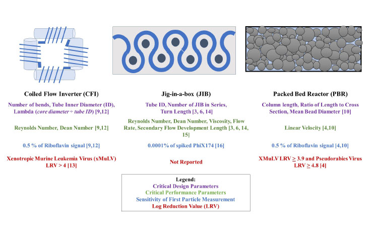
Current incubation chamber technologies for iVI belong to two categories: cyclical flow reactors (CFR) and packed bed reactors (PBR). Coiled tubing used in a CFR design decreases the RTD by inducing secondary flow motions.6 ,7 Two CFRs have been developed for iVI: the coiled flow-inverter (CFI), developed by Bayer,8 and the serpentine tubular flow device (jig-in-a-box, or JIB), developed by Boehringer-Ingelheim.9 The CFI comprises a series of helical coils arranged at right angles, while JIB is designed with a flow path of alternating 270-degree turns.6

Alternatively, the PBR uses a packed bed of nonporous, inert beads to minimize the RTD. The RTD is dependent on different critical design and operating parameters specific to each incubation chamber technology.4 ,10 ,11 Therefore, a mechanistic understanding of the parameters that affect RTD is necessary to guarantee robust performance. Chamber performance is characterized by injecting pulses of tracer molecules into a flow path and measuring the dispersion of the pulse exiting the chamber. This information is used to generate metrics for the chambers, as shown in Figure 2. Upon chamber commercialization, the data provided on RTD and VI will enable manufacturers to select a suitable chamber for their process needs.

LC i System Implementation

Manufacturers need to consider process-associated challenges and possible mitigation strategies for successful implementation of an iVI system.

Post–Protein A Process

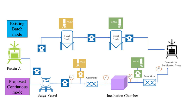
Eluate from the protein A affinity capture may deliver a variable feed profile to the iVI process, which can be challenging to control because acid titration is dependent on both inlet feed concentration and pH. Titration methodologies must be established that enable the system to react precisely to the incoming feed conditions. A feedback loop could utilize inline pH and protein concentration measurement to adjust the acid injection rate dynamically as concentration changes in order to bring the feed to the target pH. Alternatively, installing a surge vessel post–protein A (Figure 1) would allow the pooling of the eluate to provide a more homogeneous protein concentration to be delivered for titration. Additionally, a surge vessel would mitigate the risk of negative impact caused by possible process interruption. 12 ,13 ,14 ,15

Manufacturers need to consider process-associated challenges and possible mitigation strategies for successful implementation of an iVI system.

pH Sensor Accuracy and Stability

Accurate pH measurement is required to ensure the feed reaches the target pH for VI. During operation, pH sensors can drift or lag, which may result in an incomplete VI. An incomplete VI is associated with pH inaccuracy.16 Strategies to minimize risk include well-characterized, robust sensors with defined operational limits and extensive pH stability performance data collected over extended periods of operation. Additionally, a system design that enables sampling for offline pH measurement would provide the capability to perform a single-point readjustment of the online pH reading. Periodic sensor recalibration will be an important operational requirement.

Incubation Chamber Size

The iVI system must provide a residence time that ensures exposure of the feed to the target pH for the required incubation time. Because lower incubation times risk incomplete VI, the chamber size should be adjusted to factor in the shortest residence time and desired safety margin.2 In addition to these design considerations, biomanufacturers will need to assess their process for minimum and maximum low pH exposure time, feed characteristics, and flow rate to define a chamber size that delivers the appropriate RT with a safety factor.

VI Validation Implementation

Although chamber design studies have established theoretical considerations for designing an iVI system, implementation in a manufacturing environment requires process-specific validation. With iVI, two possible strategies for validating efficacy of the VI process include:

  1. Perform validation studies in the inline operating mode using a small-scale chamber with a fluid flow profile equivalent to the process-scale chamber and that encompasses the range of design and operating parameters of process scale. Data from spiking studies generated on the scale-down model can be used to demonstrate the required VI. System-induced virus loss from mechanisms such as shear or adsorption loss should be quantitated so that the claimed LRV can be solely attributed to low pH.
  2. If the iVI process uses an incubation chamber with a flow profile that has been well characterized, viral inactivation can be validated using established static hold methods combined with a knowledge of the experimentally-determined minimum residence time (MRT) of the selected process-scale incubation chamber. This validation will require the supplier to characterize the MRT for the range of conditions under which the chamber can be operated. In addition, this validation may require an initial body of work by the supplier to prove an equivalent LRV in iVI compared to static VI at the same exposure times.4 ,7 ,9

Conclusion

The biopharmaceutical industry is innovating to meet increasing production demands while assuring patient safety. Transitioning from batch manufacturing processes to continuous operating modes embodies this objective, enabling flexible and streamlined manufacturing. As a critical piece of the overall virus control strategy for biotherapeutic production, low pH virus inactivation can be successfully integrated into a continuous processing train by ensuring that the critical parameters of pH and incubation time are robustly controlled.

Major challenges of implementing continuous processing operations include robust sensing and maintenance of operational requirements, managing heterogenous feed inputs, and process validation. Recent advances in incubation chamber design, along with an increased understanding of key considerations for robust design and control of iVI systems, are big steps toward facilitating the adoption of fully continuous biomanufacturing to improve patient access to life-saving therapies.

  • 6 a b Parker, S. A., Amarikwa, L., K. Vehar, R. Orozco, S. Godfrey, J. Coffman, P. Shamlou, and C. L. Bardliving. “Design of a Novel Continuous Flow Reactor for Low pH Viral Inactivation.” Biotechnology and Bioengineering 115, no. 3 (2018): 606–616. doi:10.1002/bit.26497
  • 7 a b Klutz, S., S. Kutup Kurt, M. Lobedann, and N. Kockmann. “Narrow Residence Time Distribution in Tubular Reactor Concept for Reynolds Number Range 10-100.” Chemical Engineering Research and Design 95 (2015): 23–33. doi:10.1016/j.cherd.2015.01.003
  • 8David L., B. Maiser, M. Lobedann, P. Schwan, M. Lasse, R. Horst, and G. Schembecker. “Virus Study for Continuous Low pH Viral Inactivation Inside a Coiled Flow Inverter.” Biotechnology and Bioengineering 116, no. 4 (2019): 857–869. doi:10.1002/bit.26872
  • 9 a b Orozco, R., S. Godfrey, J. Coffman, L. Amarikwa, S. Parker, L. Hernandez, and C. Wachuku. “Design, Construction, and Optimization of a Novel, Modular, and Scalable Incubation Chamber for Continuous Viral Inactivation.” Biotechnology Progress 33, no. 4 (2017): 954–965. doi:10.1002/btpr.2442
  • 4 a b
  • 10Sencar, J., N. Hammerschmidt, D. L. Martins, and A. Jungbaer. “A Narrow Residence Time Incubation Reactor for Continuous Virus Inactivation Based on Packed Beds.” New Biotechnology 55 (2020): 98–107. doi:10.1016/j.nbt.2019.10.006
  • 11Arnold, L., K. Lee, J. Rucker-Pezzini, and J. H. Lee. “Implementation of Fully Integrated Continuous Antibody Processing: Effects on Productivity and COG.” Biotechnology Journal 14, no. 2 (2019): 1–10. doi:10.1002/biot.201800061
  • 12Brown, M., R. Orozco, and J. Coffman. “Leveraging Flow Mechanics to Determine Critical Process and Scaling Parameters in a Continuous Viral Inactivation Reactor.” Biotechnology and Bioengineering 117, no. 3 (2020): 637–645. doi:10.1002/bit.27223
  • 13Amrikwa, L., R. Orozco, M. Brown, and J. Coffman. “Impact of Dean Vortices on the Integrity Testing of a Continuous Viral Inactivation Reactor.” Biotechnology Journal 14, no. 2 (2019). doi:10.1002/biot.201700726.
  • 14David, L., L. M. Waldschmidt, M. Lobedann, and G. Schembecker. “Simulation of pH Level Distribution Inside a Coiled Flow Inverter for Continuous Low pH Viral Inactivation.” Biotechnology and Bioengineering 117, no. 2 (2019): 429–437. doi:10.1002/bit.27201
  • 15Brown, M., and R. Orozco. “Utilizing Bacteriophage to Define the Minimum Residence Time Within a Plug Flow Reactor.” Biotechnology and Bioengineering (2021): 1–8. doi:10.1002/bit.27734
  • 16Goby, J. D., K. Furuya, E. Zimmermann, J. A. Beller, J. M. Schmitt, M. Cortese, J. F. Breit, and J. L. Coffman. “Feasibility of Spectral pH Measurement During the Low-pH Virus Inactivation Step of Continuous Therapeutic Antibody Production.” Biotechnology Progress 36, no. 4 (2019): 1–14. doi:10.1002/btpr.2988
  • 2