Continuous Manufacturing of Small Molecule Drug Substances

The adoption of continuous manufacturing (CM) in the pharmaceutical industry is increasing because of the advantages and opportunities it offers, including the ability to handle hazardous reactions, a higher degree of process integration, and improved sustainability. This article discusses the considerations and approaches adopted by Pfizer, Eli Lilly, GSK, and Amgen in designing and implementing their small molecule drug substance (DS) CM processes and some key contrasts relative to existing CM approached for drug product (DP).
Continuous manufacturing (CM) is gaining traction in pharmaceutical manufacturing. In June 2022, we published an ISPE iSpeak blog, Contrasting Drug Substance and Drug Product Continuous Manufacturing, to highlight some of the key differences between small molecule DS and DP CM. The blog emphasizes the fact that there is no one-size-fits-all to developing CM processes, because of the differences between DP CM and DS CM. The following lists five attributes of integrated DS CM processes that were highlighted:
- Diverse unit operations and equipment configurations. In DS production, numerous and diverse sets of unit operations (e.g., reactors, extractors, evaporators, crystallizers, filters) and a unique equipment arrangement can be used for a given synthetic step.
- Mean residence time (MRT). Although reactions may have short reaction times and correspondingly short MRTs, integrated DS CM processes often include surge tanks and continuous stirred tank reactors (CSTRs) and workup/isolation units operating with longer MRTs; these overall integrated processes therefore tend to have a longer combined MRTs broader residence time distributions (RTDs) and may also have correspondingly longer startup and shutdown transition times.
- Continuous operation time. Because of the first and second attributes, DS CM processes are commonly operated over longer runtimes than DP CM processes and collect a larger number of batches without stopping and restarting.
- Isolation of DS and batching strategy. For DS processes, it is common to couple continuous reactions and crystallization operations with semi-batch isolation, washing, and drying unit operation, resulting in discrete lots and batches of DS or drug substance intermediate (DSI) discharged during a continuous run.
- Miniaturization and development. In DS CM processes, the reactors and unit operations can be miniaturized to a greater extent than for DP operations, which is beneficial for development and characterization activities.
In this article, we expand on this by providing select examples from the small molecule DS development and manufacturing histories at Pfizer, Eli Lilly, GSK, and Amgen.
Pfizer: CM Process for a Late-Stage Product
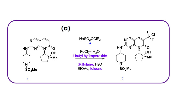
Pfizer recently developed a CM process for a late-stage product to open new chemical space and access the most cost-effective and sustainable route to the active pharmaceutical ingredient (API). This was motivated by a difluorochloromethylation reaction, shown in Figure 1A, that provided rapid access to a key intermediate but that could not be easily scaled in batch due to a low thermal onset of both reagents and intermediates, heat transfer limitations to manage the highly exothermic reaction, mass transfer limitations to ensure a high-yielding reaction, and the need for a rapid quench and extraction to manage a relatively unstable intermediate reaction mixture.
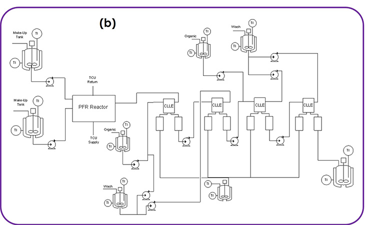
These challenges were all overcome by developing the integrated CM process shown in Figure 1B, which could be scaled. The process was originally developed by conducting the reaction in a plug flow reactor (PFR) more safely, quenching in a CSTR, and then separating and washing the organic phase twice through continuous centrifugal extractors (known as continuous liquid–liquid extractors, or CLLEs). A microreactor was used for the PFR to ensure excellent heat and mass transfer. The process was developed for manufacturing ensuring a high-yielding process and high-quality product. This example illustrates the attributes we have highlighted for CM DS processes, as expanded on next.
Figure 1: (1A) chemical scheme and (1B) process flow diagram for an integrated CM process developed at Pfizer, enabling the execution of a difluorochloromethylation reaction that provided rapid access to a key intermediate in a late-stage product.
Diverse Unit Operations and Equipment Configurations
For the single DS synthesis step shown in Figure 1, we require a diverse collection of equipment, including PFR, CSTR, and CLLE. This can be implemented by configuring the modular equipment tool kit established at Pfizer, which we call the Flexible API Supply Technologies (FAST). Upon delivery of this product, the equipment can be cleaned and reconfigured for other products in the Pfizer portfolio.
MRT
The MRT for the reaction is around 40 seconds and less than 60 seconds for each liquid–liquid extraction stage. However, due to the use of unstirred organic collection vessels after each liquid–liquid extraction stage, the RTD is somewhat longer than a typical DP process. The startup and transition time is relatively short for this process because the reaction is incredibly fast.
Continuous Operation Time
To date, the process has been run at 4 kg/day throughput but could be increased to between 10 to 20 kg/day for commercial manufacturing using relatively small-scale equipment. To produce the desired commercial volumes of API, it would need to be run continuously for around 200 days at the estimated peak demand. Although batch size is determined by downstream batch equipment, the CM process allows us to adapt to moderate changes in demand by running the process for longer or shorter periods each year.
Isolation of DS and Batching Strategy
Following the CLLE operations shown in Figure 1, the process then moves to batch distillation, crystallization, and isolation. This provides a natural batching strategy, sized based on the isolation equipment capacity. Strategically, these batches could be moved to continuous distillation, crystallization, and isolation, which would allow for integration into other continuous steps within the synthesis. This would further increase MRT and RTD but would ultimately lead to a significant cycle time improvement for the overall synthesis, in addition to delivering a more sustainable, high-quality, and cost-effective process compared to a batch process.
Miniaturization and Development
The process was developed on a laboratory-scale system capable of producing 200 g/day. The scaleup from laboratory to plant was highly effective, with comparable heat and mass transfer observed on the manufacturing equipment.
Eli Lilly: CM Process for API Manufacturing
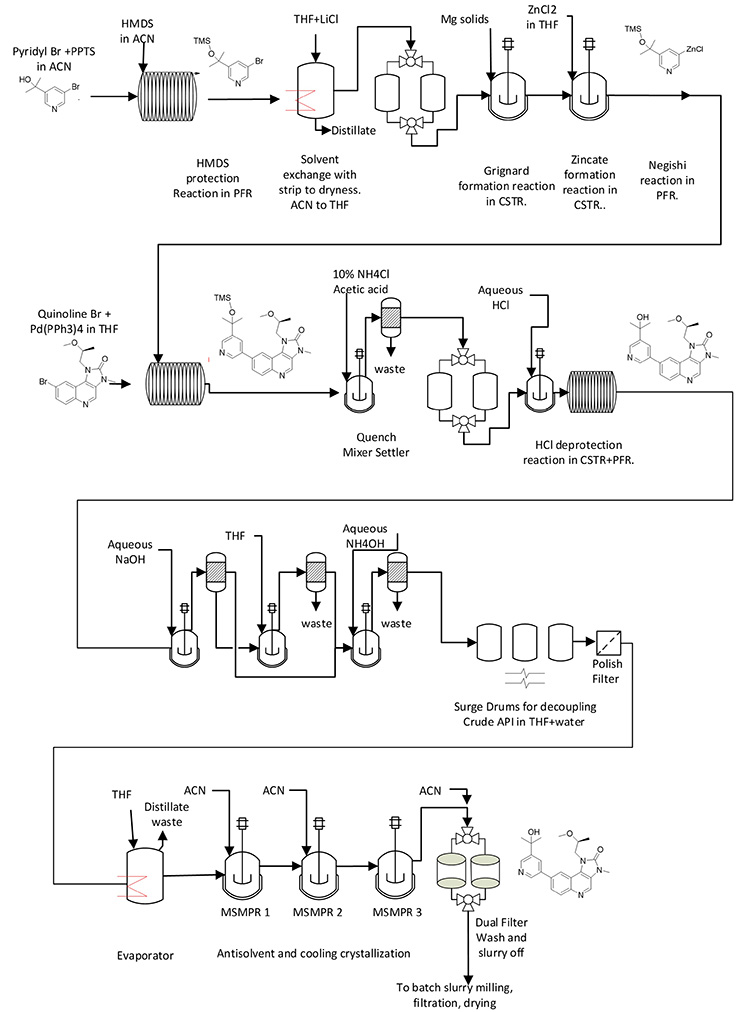
An integrated CM process was operated at Eli Lilly to make 204 kg of API material using GMP for first registration doses in clinical trials.1 Figure 2 shows the process flow diagram with the chemical integrated into the diagram. A manuscript is in preparation that describes the benefits for continuous Grignard reagent/zincate synthesis and Negishi coupling reaction.2 In short, safety and quality are better when the synthesis is run continuously. As with the previous example, this example can help illustrate the common attributes of DS CM processes.
Figure 2: Synthetic scheme and process flow diagram for integrated CM process at Eli Lilly.
Diverse Unit Operations and Equipment Configurations
The process flow diagram shown in Figure 2 is significantly different from that shown in the previous example from Pfizer (see Figure 1). This helps illustrate the diverse set of unit operations and equipment configurations in DS CM processes. In particular, this example requires three PFRs, three CSTRs, three extractors, two evaporators, three mixed-suspension mixed-product-removal (MSMPR) crystallization vessels in series, dual filters, and three surge points, as these are connected together.
MRT
This complex integrated process provides a good example of compounding MRTs. For each reaction run in the PFRs, the MRTs were 0.5 to 2 hours. Additionally, the CSTRs had MRTs from 0.5 to 3 hours, and each extractor had an MRT between 0.5 and 1 hour, whereas the MRT of the evaporators was 1 to 2, and the MRTs of the MSMPRs was between 2.5 and 4 hours. When combined, this gives a lengthy process MRT and startup transition time.
The total MRT was 67 hours, with about 27 hours of MRT in the reactors and separators and 40 hours in the surge vessels. The RTD for 99% push out of material entering the beginning of the flow train spanned about one day. And finally, total startup transition time to fill the entire train with process materials, for guidance, was about 80 hours. A small amount of material was diverted to waste during startup and shutdown transition time for each of the three main PFRs, but most of the process was started and shut down with no diverting to waste.
Continuous Operation Time
The total runtime for the registration stability campaign executed for this process was 29 days. The runtime was intended to be consecutive, but there were several flow stoppages for troubleshooting. Target nonstop runtime for this process in commercial manufacturing is six months.
Isolation of DS and Batching Strategy
The final section of the flow train, including distillation, crystallization, and filtration, ran under fully parametric control. API was discharged from the dual filters into the downstream batch milling, with filtration drying operations occurring once every 30 minutes. The slurry collection tank downstream from the dual filters collected material for about two days for each batch. The first few batches included startup transition material, and the last few batches included shutdown transition material.
Miniaturization and Development
Development scale was on the order of 100 times smaller than plant scale for the crystallizers, extractors, and CSTRs, and more than 1,000 times smaller for the PFRs.
GSK: Continuous Commercial Process Implemented
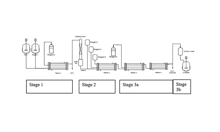
Figures 3 provides the process flow diagram for one of the two commercial semicontinuous processes operated by GSK at their Jurong Singapore campus. The process is a second generation of an original six-stage batch process for a respiratory medicine to treat chronic obstructive pulmonary disease. This is the only example of a commercialized process in this article.
Figure 3: Process flow diagram for CM process at GSK.A picture containing sketch, diagram, technical drawing, plan
Diverse Unit Operations and Equipment Configurations
This example illustrates three consecutive telescoped chemical reactions performed in PFRs, which are “bookended” by upstream and downstream batch unit operations. For this operation, the range of unit operations include substrate solution preparation (which is a batch operation), three consecutive PFR chemical reactions with no workups and isolations in between, and batch crystallization, filtration, and drying at the end.
MRT
The MRTs for the chemical reactions of stages 1, 2, and 3 are approximately 20 minutes, 40 minutes, and 20 minutes, respectively, to drive reactions to completion while minimizing impurities generation. However, even with these relatively short MRTs, the startup time is considerable because material is diverted to waste until a defined state of control has been reached; in normal operations, nine hours are required from startup to the first drop of crude solution.
Continuous Operation Time
The GSK facility campaign time is typically a couple of months, which is significantly longer than that of continuous oral solid dose DP manufacture. The facility was designed to run continuously for 300 days/year manufacturing 3 tons/year of the DS. This long, continuous operation time is important because the startup and shutdown transition materials are not collected, making it uneconomical to stop and restart in between batches.
Isolation of DS and Batching Strategy
In this example, the stream from the final PFR is collected and processed forward through batch crystallization, filtration, washing, and drying. The batching strategy and size were therefore dictated by the batch equipment size and cycle time through these final operations.
Miniaturization and Development
Reactors and unit operations can be miniaturized to a great extent for development activities. As a bridge between small-scale operations and commercial operations, the UK research and development facility, in which this process was further developed after lab experiments, was built at 25% scale of the commercial facility. At the larger development scale, it would have been possible for the same kit to be used for process development and commercial supply.
Amgen: CM Process for a Commercial Asset
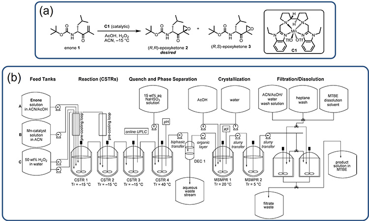
At Amgen, an integrated CM process was developed for a (R,R)-epoxyketone 2, which is a DSI in the synthesis of the commercial product carfilzomib (Kyprolis).3,5 Figure 4A shows (R,R)-epoxyketone 2 and the chemical scheme for the manganese-catalyzed epoxidation that produces this DSI from the compound enone 1. This process uses hydrogen peroxide as the stoichiometric oxidant and has the challenge of being strongly exothermic nature, with a heat of reaction of almost −250 kJ/mol and an adiabatic temperature rise (ART) of 60°C.4
Considering this chemistry, the integrated CM process shown in Figure 4B was developed to provide a flexible manufacturing option that could be used to ensure commercial supply under varying demand forecasts without changing the reactor size (important for this highly exothermic reaction). The example provides additional illustration of the common attributes highlighted for integrated CM processes for DS production; these attributes are detailed in the following paragraphs.
Figure 4: (4A) Synthesis of (R,R)-epoxyketone 2 by epoxidation of enone 1. (4B) Process flow diagram for the manufacture of (R,R)-epoxyketone 2, a DSI in the synthesis of carfilzomib (Kyprolis). Reprinted from.4
Diverse Unit Operations and Equipment Configurations
The integrated process shown in Figure 4 contains nine processing vessels, nine feed tanks, and a product-collection vessel, along with eleven pumps to transfer single-phase solutions, slurries, and biphasic mixtures. The setup is used to execute the primary reaction (in a series of CSTRs), enable continuous quench and phase separation workup going into a water-driven continuous antisolvent crystallization followed with filtration, washing, and dissolution to yield the product in a methyl tert-butyl ether (MTBE) solution.
MRT
Figure 4 shows six stirred vessels operating as CSTRs or MSMPR crystallizers. The three CSTRs used to conduct the primary reaction each had a MRT of 15 minutes; the final CSTR used to quench and work up the reaction stream had a MRT of 40 minutes. The two MSMPR vessels were operated with MRTs between 30 and 45 minutes, and the final filtration, washing, and dissolution operations were conducted with parallel batch filtration units, operated in a semicontinuous batch in tandem, with the cycle times dictated by the size of the batch filtration units. This gives an MRT of 175 minutes through the continuous process operations. Further, as each stirred tank can be well agitated, the RTDs for each CSTR/MSMPR could be considered ideal, given an overall convoluted RTD with a very long tail.
Continuous Operation Time
Even with fast reactions, the combined six stirred vessels and phase-split workup operation result in a significant startup time. As a consequence, it is economical to operate the process continuously in a state of control for as long as possible. In this case, the aim was to run the process continuously throughout the year with as few as two shutdowns depending on DS demand.
Isolation of DS and Batching Strategy
For the process shown in Figure 4, isolation was achieved through filtration in dual-batch filtration units. The isolated product was then washed and dissolved in MTBE to be transferred to a product tank. This allowed for numerous batching strategies; however, it was intended that batches would be specified by production runtime, with sub-lots specified by the desired size of the product drums.
Miniaturization and Development
The lab development of an integrated CM process for the carfilzomib DSI was largely done with small-scale batch reaction, workup, crystallization, and filtration setups ranging from 3 to 100 mL.
Discussion
There is no specific one-size-fits-all approach to DS CM, but there are some general attributes that distinguish CM process for DS production from those for DP production.
Here we highlighted how each DS CM flow train is expected to have different unit operations and equipment configurations, specific to what is required for the synthetic step. CSTRs in series were used for reaction steps in the Amgen example, PFRs in series in the GSK example, and a combination of PFRs and CSTRs in the Eli Lilly and Pfizer examples.
Separations unit operations included gas stripping column, liquid–liquid extraction, distillation, and crystallization, and each example had a unique selection and arrangement of them. Even for the same type of unit operation, equipment selection and MRT can be quite different. For the liquid–liquid extractions, the Pfizer example used centrifugal extractors with an MRT of 60 seconds followed by settlers with longer MRT, whereas the Eli Lilly example used mixer settlers with an MRT of one hour each. The choice and type of unit operation depend on process needs and limitations.
We also illustrated how the MRTs can be extended for integrated CM DS processes that link together these operations. The number of continuous unit operations in series ranged from three to twelve in the four examples given. The MRTs in PFRs ranged from 40 seconds in the Pfizer example to two hours in the Eli Lilly example, as required by the different chemistry. With the MSMPR crystallizers, the MRTs ranged from 30 minutes in the Amgen example to four hours in the Eli Lilly example, likely because of the difference in crystallization nucleation and growth rates for each process. Linking these together resulted in total integrated process MRTs as short as 175 minutes and as long as 67 hours.
Target runtimes for the described DS CM processes ranged from one to ten months. Provided no technical challenges are encountered, continuous runtimes will be dictated by operational considerations at the manufacturing site and by the demand for the DS or DSI. All else being equal, it is economical to run continuously for as long as possible. This is also in accordance with ICH Q13, which states, “…batches could be obtained with a single start-up/shutdown sequence” and “a single planned start-up and shutdown of the commercial CM system was used to manufacture the process validation batches.”5
In each example, the isolation of the DS or DSI was accomplished through a batch operation or in tandem semi-batch operations. The batching strategy, in each case, was then driven by the size and cycle time of the batch or semi-batch equipment used for isolation rather than the continuous runtime.
Development was done at manufacturing scale in certain circumstances, such as the PFRs in the GSK example, and it was done in PFRs 1,000 times smaller than manufacturing scale, as stated in the Eli Lilly example. This is in line with ICH Q13, which suggests, “development work [can occur] on smaller equipment” but also that “there is an opportunity to generate development knowledge at the same scale intended for commercial manufacturing.”5
Conclusion
As DS CM processes gain traction in the industry, we continue to gain valuable insights about how this mode of manufacturing can best be used to flexibly and reliably deliver pharmaceutical DS. In addition, we expect integrated CM processes to continue to evolve and demonstrate business benefits relative to batch for target synthesis steps. This manuscript shares four case studies of integrated CM processes developed for small molecule DS production at Pfizer, Eli Lilly, GSK, and Amgen, and uses those to highlight common attributes. The intent is to encourage open dialogue across the industry and collective learning in this rapidly evolving field.
About the Authors


