A Simplified Integration of Qualified Laboratory Devices with the Asset Administration Shell as the Digital Twin

This Concept Paper proves a laboratory device integration utilizing the Asset Administration Shell (AAS) metamodel (agnostic to the underlying technology and data structure).
Abstract
Plug & play in general describes a piece of equipment that is ready to use upon connecting to a computer without any configuration, like a home printer. Plug & produce has the same vision for manufacturing and aims to enable straightforward integration of new production equipment or a device to substitute or adapt assembly line parts.
Concepts like SiLA (Standardization in Lab Automation) or OPC UA/LADS (Laboratory and Analytical Device Standard) are the groundwork for the standardization of interfaces and data formats of laboratory devices to enable Plug & Produce. However, current standards focus either on technical integration concepts or on information structures. To realize a true Plug & Produce concept, the technical integration, information structure, and pharmaceutical-specific documentation, need to be in place.
This Concept Paper proves a laboratory device integration utilizing the Asset Administration Shell (AAS) metamodel (agnostic to the underlying technology and data structure).
1 Introduction
1.1 Aim of the Proof of Concept
The pharmaceutical industry has undergone a significant digital transformation toward Pharma 4.0™ in recent years. Nevertheless, many pharmaceutical companies are still struggling to keep pace with digital transformation mainly because of brownfield installations, which are difficult to integrate. The focus on digital improvements has been on the production areas, which got a big push with the Industry 4.0 (I4.0) concept. For pharmaceutical production, the laboratory area with its Quality Control (QC) and release processes is equally important but has not had the same level of attention in recent years.
During the COVID-19 pandemic, many pharmaceutical companies realized the challenges of remote QC and release processes. Additionally, while laboratories for QC and release play an essential role, they face an even higher complexity regarding laboratory equipment and their connectivity than in current manufacturing areas.
Increased productivity requirements are also seen in the laboratory area, whereas today the process is still a widely manual paper-based process with limited improvement potential. Many proofs of concept or initial projects have been started to drive the digital transformation beyond the classical Laboratory Information Management Systems (LIMS) and electronic laboratory notebooks. Not only do these projects focus on the seamless integration of laboratory equipment to different systems to improve compliance and data integrity, they also aim reduce QC as a possible bottleneck in the time-to-market process for pharmaceutical products. With the advance of personalized therapies, this could lead to substantial cost reduction in production with a significant impact on the market price. Additionally, this digital concept can support the ramp-up of new facilities by supporting the flexible adaptation of new and existing equipment.
The variety of laboratory equipment and vendors has led to complex integration scenarios. The situation is comparable to the complexity seen in the production area before standardization approaches like OPC UA1 started to solve the challenges of integration and reduce the corresponding efforts.
The limited integration capability in the laboratory area also leads to the development of different technological standards (e.g., SiLA 21, LADS 2), which are supported by multiple vendors but currently are not widely distributed in pharmaceutical laboratories.
From a pharmaceutical company perspective, the different integration scenarios still add up to high complexity, slowing down the technical adaptation toward digital transformation. The need for flexible and fast adaptation in the new production fields such as in biotechnology or cell and gene therapy forces companies to integrate in a customized way. This leads to high costs and efforts, not only during implementation but also during the lifecycle of the equipment and IT systems and their environment.
Business stakeholders no longer accept locked-in data or data silos between functional departments or within the overall organization. The expectation is that data from laboratory equipment can be read, identified, and added to different on-premise tools or even enterprise IT systems in the cloud (see Figure 1.1).
Figure 1.1: Expectations from Business Stakeholders
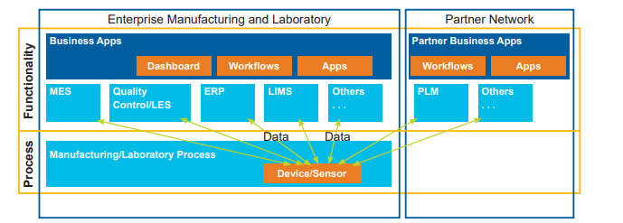
| Key: | ERP: Enterprise Resource Planning | LES: Laboratory Execution System | PLM: Product Lifecycle Management |
| LIMS: Laboratory Information Management Systems | MES: Manufacturing Execution System |
This Concept Paper applies an innovative concept for pharmaceutical-specific regulatory requirements and an Industry of Things (IoT) framework that gives a 100% horizontal and vertical integration. This concept provides innovative ideas to overcome existing challenges with proven vendor-agnostic concepts without being limited to specific technologies.
1.2 Scope of the Proof of Concept
The existing and widely adapted concept of “Industry 4.0” in different industries provides a framework to improve interoperability on the way to digital transformation. This Concept Paper describes a successful Proof of Concept (PoC) to utilize the Digital Twin (DT) concept “Asset Administration Shell (AAS)” for pharmaceutical laboratory environments. This standardized integration approach improves the configuration activities and therefore the integration capabilities of equipment into central systems like ERP, LIMS, and other manufacturing-related IT systems, as well as the link to partners with cloud-based solutions. The concept is adapted to the specific requirements of the lifecycle of laboratory instruments, devices, and tools not only to simplify initial implementation, but also to improve lifecycle management with regular exchanges or updates that support the compliance requirements of the pharmaceutical industry.
In an integrated digital platform, every change leads to additional qualification and validation efforts. The costs and time for these changes are often considered unjustifiable when aiming to adapt to process changes and support the security requirements of modern IT architectures. Additionally, pre-validated equipment can rarely be used because of individual implementation requirements. To be able to speed up the digital transformation toward Pharma 4.0, new concepts and out-of-the-box thinking are necessary.
To show a feasible way forward for pharmaceutical companies, device and software suppliers, and implementation partners, a joint effort was undertaken to create a PoC with the following user story:
As a Laboratory Operator, I have an instrument (e.g., scale or robot) connected to my LES or LIMS systems. In case of a failure, the Laboratory Operator can exchange a prequalified instrument without any configuration in any system to be able to continue the work immediately and reduce the requalification efforts ideally to zero.
This target should be achieved with a standardized but adaptable device description with the I4.0 concept “Asset Administration Shell (AAS).” The AAS is the digital representation of the asset and provides an interface to the network allowing communication with other assets and exchange of information (see Figure 1.2). The Translation Layer orchestrates and contextualizes the information between different participants of the communication, so the individual communication partners can receive all necessary information from this layer.
Figure 1.2: Target Solution Architecture
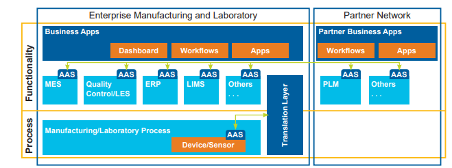
| Key: | ERP: Enterprise Resource Planning | LES: Laboratory Execution System | PLM: Product Lifecycle Management |
| LIMS: Laboratory Information Management Systems | MES: Manufacturing Execution System |
The functionality, data structures, and connectivity of laboratory instruments can be standardized with this concept, so the target of a plug & play configuration could be achieved where even pre-validated solutions can be used, and major parts of the validation/qualification activities can be outsourced to the supplier.
The focus of the PoC was the overall administration and management concept to achieve the goal of supplier-agnostic instrument integration in the regulated pharmaceutical industry. The concept should represent the equipment as a DT in a real environment. Since the technical integration is based on established technologies and should support multiple industry standards, it was not part of the main scope of the evaluation.
The following chapter explains the DT with the AAS concept in more detail (Chapter 2). Afterward, the technical setup and components of the PoC are explained (Chapter 3). This Concept Paper closes with a summary and an outlook on the next steps (Chapter 4).
2 Digital Twins and Asset Administration Shell
2.1 Definition of Digital Twin
The DT concept was first presented by Grieves and Vickers as a “Conceptual Ideal for product lifecycle management (PLM)” 3. It depicts the connection between the physical device, represented in the Real Space, and the DT in the Virtual Space. Ideally, the DT has all aspects of the real device and tries to be as accurate to the Real Space as possible. The physical device sends all data about itself to the DT, which, in perfect condition, not only holds the current, but also the historical data.
The information gathered in the Virtual Space is sent back to the device to allow for remote control and access.
2.2 Asset Administration Shell
2.2.1 General
DT and Cyber-Physical Systems (CPS) try to create ways for interaction and interoperability between companies, their partners, and whole industries 4. To achieve this goal, these concepts need to have standardized specifications and implementation. Standardizations include a concrete definition of the data formats, which need to be serializable, and their interfaces, to allow for seamless integration in different scenarios. Additionally, the semantic meaning of connected objects in the real world and other attributes must be part of the standardization 4. This not only allows the implementations to be interchangeable but also facilitates communication between products of all industry partners since each party involved uses the same definitions.
The AAS is one such definition for DT in the Industry 4.0 (I4.0) context. It was defined by the Plattform Industrie 4.0 as a specification for an industry-ready DT 5. However, it is also utilized for other industry concepts like Pharma 4.0.
Figure 2.1 shows how an AAS is used and transferred between a supplier and an integrator. The supplier creates the AAS for their assets (product D1 with two different product types A1 and B1) and sends those to the integrator. The integrator can, in turn, use them to create a new composite AAS C1 (see in Figure 2.2) representing their newly created product (D2) that utilizes all included assets.
Figure 2.1: Concept of the Asset Administration Shell (Adapted from S. Bader et al 6)
![Figure 2.1: Concept of the Asset Administration Shell (Adapted from S. Bader et al [6])](/sites/default/files/concept-papers/Simplified%20Integration/Figure%202.1%20Concept.PNG)
2.2.2 Structure
Tantik and Anderl 7 used the requirements for the AAS to roughly define its structure by creating a frame of several segments that try to solve the problems facing an AAS. Figure 2.2 shows these segments and how they are interconnected. Both sides of the AAS have interfaces, one for external communication and one for internal. The external interface is used as a bridge to all other components of the Pharma 4.0 system. As a result, the interface must be highly standardized to allow for a connection between all components and at the same time be interchangeable.
Figure 2.2: Structure of the I4.0-component according to Tanktik and Anderl
(Adapted from M E. Tantik and R. Anderl 7)
![Figure 2.2: Structure of the I4.0-component according to Tanktik and Anderl (Adapted from M E. Tantik and R. Anderl [7])](/sites/default/files/concept-papers/Simplified%20Integration/Figure%202.2%20Structure.PNG)
2.2.3 Metamodel
The Reference Architecture Model Industrie 4.0 (RAMI 4.0) 8 is a generalization of the most important characteristics of I4.0 concepts, created to achieve a common view and understanding of all business aspects. It incorporates three unified viewpoints – the product lifecycle, the factory hierarchy, and the communication layer – into one illustration. This is to break the problem down into smaller and more manageable problems, thus allowing for specialization for each use case. These ideas can also be applied to Pharma 4.0 as it faces similar problems in digitizing all the different assets in use in the industry.
Similarly, the Industrial Internet of Things (IIoT) concepts are applicable, focusing on reducing the number of steps needed for all assets to communicate with each other. Figure 2.3 shows the automation pyramid based on the ANSI/ISA-95 standard 9. It has strict communication paths that only allow each layer to communicate with its adjacent layers. This restriction is lifted with the new hierarchy model of the I4.0 concept. This concept allows for direct communication between different elements of each layer, thus creating a flexible factory. Additionally, the concept allows for direct communication outside of company boundaries, which in turn enables direct feedback channels and shorter reaction times between all layers. Furthermore, since the renewal of old systems is a continuous process, the I4.0 does not require a complete overhaul of existing systems, but rather step-by-step adaptations.
Figure 2.3: From ISA 95 Enterprise Level Model to Industry 4.0 Global Multidimensional Model 9
![Figure 2.3: From ISA 95 Enterprise Level Model to Industry 4.0 Global Multidimensional Model [9]](/sites/default/files/concept-papers/Simplified%20Integration/Figure%202.3%20From.PNG)
2.3 BaSys 4 and Eclipse BaSyx Open-Source Communication Middleware
2.3.1 BaSys 4
With the transformation of the pharmaceutical industry to Pharma 4.0, there is a need for solutions to allow for the switch without leading to complications. One such solution is the open-source BaSys 4 concept 10 developed as a general I4.0 solution, which can be extended for use in the pharmaceutical domain. BaSys 4 defines an architecture for production systems and thus the architectural changes needed in a production system to allow for the adoption of Pharma 4.0.
Adaptable manufacturing, being one of the goals of both I4.0 and Pharma 4.0, can be enabled through the ideas of BaSys. This includes the reduction of lot sizes to meet specific requirements and changing processes to accommodate a more individualized production approach.
2.3.2 Eclipse BaSyx Open-Source Middleware
As the reference implementation of BaSys 4, Eclipse BaSyx 11 allows for the digitalization of facilities utilizing the ideas of the AAS. The communication middleware is provided under an open-source MIT license and can be easily integrated into existing middleware solutions. The reference implementation with Eclipse BaSyx can be utilized to achieve the ideas of Pharma 4.0. In its architectural style, the communication middleware relies on the ideas of service-oriented architecture, creating services that can be reused by different actors, e.g., an ERP-System. To achieve this goal, the middleware allows for direct communication between physical assets and various parts of the IT systems in place. Figure 2.4 shows this connection between the different components of Eclipse BaSyx and the IT systems.
Figure 2.4: Overview of the Eclipse BaSyx System Structure (Adapted from “BaSyx Overview” 12)
![Figure 2.4: Overview of the Eclipse BaSyx System Structure (Adapted from “BaSyx Overview” [12])](/sites/default/files/concept-papers/Simplified%20Integration/FIgure%202.4%20Overview.PNG)
With the AAS and its submodels at its center, the Eclipse BaSyx middleware has a common interface for every element that is part of the entire system, the Virtual Automation Bus (VAB). As communication is managed via the VAB, different applications can utilize the data and functionality of the DT. This is achieved by the ability of the VAB to use gateways to access different network types 13, which allows for cross-network and cross-protocol communication between devices 14. The middleware also utilizes the AAS and its submodels to represent physical and digital assets as their own respective objects in BaSyx 15, which are deployed on specialized AAS servers and can be located through a specialized directory. This concept of registering the twin at a centralized directory to be found by any system also facilitates the Plug & Produce idea of automatic discovery. With Control Components as another aspect of Eclipse BaSyx, the middleware has a service-oriented structure and allows for a unified interface to the connected devices 16.
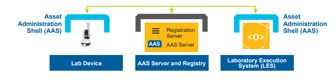
Figure 2.5 shows the general system architecture with the middleware in use. The edge node connects to the physical asset. This node can be deployed on the laboratory device itself. The first steps for the laboratory device in this architecture are the registration at the directory and the upload of the twin to the AAS server. As a result, an independent application that needs this kind of laboratory device can then contact the directory for the location of the twin of the laboratory device and connect to it via the services provided by the edge node 17.
Figure 2.5: Overview of the General System Architecture
3 Technical Setup and Components of the PoC
3.1 Technical Setup
A simple structure was chosen to show the possibilities for use in the pharmaceutical context. The setup consists of a laboratory device (in this case a mobile laboratory robot named Kevin® 18), an LES (Laboperator 19), and the Eclipse BaSyx registration server. With the help of this structure, the basic concepts for use in a pharmaceutical laboratory are evaluated and the potentials are shown. This structure was chosen because the combination of Kevin and Laboperator has been assessed in projects and in this way, it can be ensured that the PoC is not slowed down or prevented due to problems/incompatibilities in the software or hardware. (See Figure 3.1.)
Figure 3.1: Technical Setup of PoC with Components and Communication Path
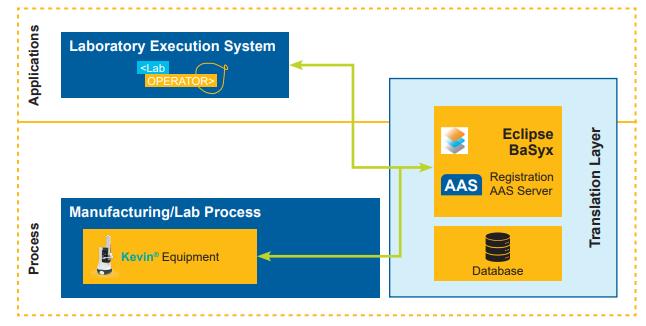
For the PoC, the existing mobile laboratory robot Kevin and LES Laboperator were adapted (clients) so that they are compatible with the concepts described. In addition, the AAS server from Fraunhofer IESE 20 was used.
The setup consists of a network with a connected WLAN access point. The robot Kevin was added to the network via Wi-Fi. Two systems are relevant for the PoC to run on the robot, the software that offers the interfaces described in Section 2.2 and the AAS server. The Laboperator box was connected to the network via LAN and has internet access to the manufacturer-specific cloud. In this way, all clients can reach the server in the network and exchange data.
3.2 Laboratory Execution System Laboperator
An LES system is software that allows processes to be conducted in a laboratory using software support. For this purpose, process flows are defined in a specific form of description and can then be conducted automatically. In most cases, it is then possible to have the steps conducted by a person or a device. For many laboratories, this is the first step toward automation, as the devices can still be used manually, but standardized processes are monitored, always conducted in the same way, and well documented.
The adaptation of the existing Laboperator client does not require any major conversion. Instead of entering the connection information directly into the client software, a mechanism was implemented that retrieves information about available devices and their functions from the registration server. This is done via the provided AAS files. The LES then uses these files to generate devices and functions that can be used in the processes. The functions can then be used in processes and new devices can be integrated quickly.
If, in addition to the exchange mechanism, there is also a standardization of the device functions, devices can be exchanged and replaced in a plug & play manner.
3.3 Mobile Robot Kevin
Kevin is a transport robot that can transport samples/consumables in microtiter-plate format between several positions in the laboratory. As stated in Section 3.1, this mobile laboratory robot was selected because it can be controlled by Laboperator in a different context. Kevin has a SiLA 2 1 and a Representational State Transfer (REST) interface already available that was used in the PoC to retrieve status information and control robot functionality.
For a device to be used in an AAS context, the device must have an AASx description. As described in Section 3.2, this contains information about the device and the control options.
The description is divided into three models:
- Laboratory robot Kevin
- Laboratory maps
- Device GxP qualification
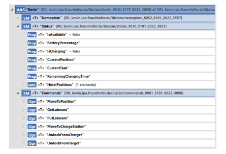
3.3.1 Submodel “Laboratory Robot Kevin”
The “Laboratory Robot Kevin” model (see Figure 3.2) includes three submodels:
- “Nameplate” is a standard template that contains information about the manufacturer, serial number, or date of manufacture. These parameters are set by the manufacturer at the time of production and are not changed throughout the product lifecycle.
- “Status” is a model that describes the current state of the robot. Information that changes frequently can be accessed here. Examples are the battery charge, the current position on the map, or the configuration of the internal hotel. Since these values change continuously, they have to be compared with the server in very short cycles.
- “Commands” submodule contains all commands that can be sent to the robot to conduct transport tasks in a laboratory or to load at the charging station.
Figure 3.2: AAS Model of “Laboratory Robot Kevin”
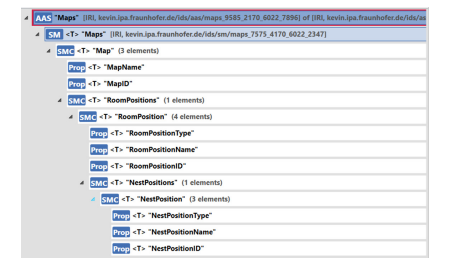
3.3.2 Submodel “Laboratory Maps”
The “Laboratory Maps” submodel (Figure 3.3) manages all information about available laboratory maps, rooms, and positions in these rooms. The data is managed in a hierarchical tree structure. These always contain the name, the ID, and a list of the associated sub-elements. Unlike the “Laboratory Robot Kevin” submodule, “Laboratory Maps” submodel can be managed centrally on a server and does not have to run on the robot. This would be the case, for example, if several systems (robots) use the positions. For easier implementation, hosting on the robot itself was implemented for the PoC.
Figure 3.3: AAS Model “Laboratory Maps”
3.3.3 Submodel “GxP Qualification” Documentation
One benefit of the AAS concept is the unlimited definition capabilities. Besides the physical representations of assets, virtual structures can also be created.
Every piece of equipment needs a specific set of information to define its qualified state. The requirements from regulatory authorities for qualification structures of equipment to be used in a pharmaceutical laboratory are widely standardized and accepted. Despite this, different quality organizations define the details slightly differently.
Two structures can be differentiated:
- Initial qualification during the installation (often supported by supplier)
- Ongoing qualification enables the qualified state to be maintained
The AAS structure (see Figure 3.4) is separated into two further submodels (SM) to represent the these aspects. Each submodel consists of additional Submodel Element Collections (SMC) to fully describe the qualification status of the respective device. The Relation Information (RelA) is used to link the Admin Shell to the actual equipment AAS model.
Figure 3.4: AAS Model for “GxP Qualification”
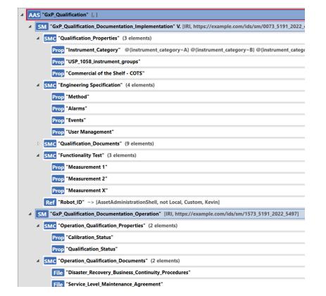
Each SMC consists of additional elements that are prefilled by the equipment vendor or will be filled during the initial qualification activities.
The digital representation of the qualification set consists of descriptive header information, engineering specifications, expected qualification documentation or representation of their data, functional test results, etc.
In combination with the AAS of the equipment, other IT systems can check the qualified state of the equipment with all relevant information. Thus, Quality organizations have a single point of truth for the qualified state of piece equipment, where qualification activities can be easily provided by the equipment vendor.
During the operation of the equipment, information can be added to the model to represent the qualified state.
3.4 Integration
With the structure of the AAS using submodels for all distinct aspects of a given asset, the devices need to update the respective submodels with their information. These submodels can be general or be specialized for different use cases, for example, a digital nameplate. After the AAS has registered itself to a directory, an application can look up its information and access the needed element directly. As shown in Figure 3.5, the dashboard application uses this feature to access the submodel with the device status directly and retrieve only the necessary information. However, the submodel does not directly pull the data from the device itself, instead, it relies on the smart device to push its status data regularly.
Figure 3.5: Architecture of the AAS in Eclipse BaSyx (Adapted from “Eclipse Wiki – BaSyx Overview” 13)
![Figure 3.5: Architecture of the AAS in Eclipse BaSyx (Adapted from “Eclipse Wiki – BaSyx Overview” [13])](/sites/default/files/concept-papers/Simplified%20Integration/Figure%203.5%20Architecture.PNG)
In the beginning, the two clients are informed of the address of the server. As soon as the Kevin client is started, it sends the initial values to the AAS server. The robot then checks repeatedly whether the status has changed and, if necessary, sends the updated AAS file to the server.
At the same time, on the LES side, after configuration, the current status can be called up from the server via the web interface and the current values of the robot are displayed on the surface.
The following steps could be successfully checked in this setup:
- Registration of devices
- Exchange of device functions
- Retrieval of the available functions
- Control of devices
- Changing and retrieving status information
- Concept for providing qualification documents
- Display of qualification status
Although the PoC does not cover all potential use cases and possible steps, the basic concepts of identification and communication were shown. The technical feasibility could be proven, and the concept shows further potential.
4 Conclusion and Outlook
This proof of concept shows the capabilities of a structured Digital Twin using the available and scalable AAS concept built on the existing meta model of the “Plattform Industrie 4.0.” The concept can be adapted and extended to individual needs based on a proven industry standard with a standardized data model. With the built-in qualification status concept, today’s documentation efforts can be significantly reduced, and change control simplified.
Using the AAS concept shows benefits for pharmaceutical production. One benefit during the implementation phase is the ability to work in parallel on both sides (data provider and data user) after defining the AAS. This is possible because the mandatory components still exist and can be used directly. The Eclipse BaSyx AAS server in this PoC provides interfaces to test the implementation directly against the server. Another benefit is the interpretable and usable format of the AAS, which is well structured and human and machine readable.
The AAS for GxP qualification is the draft of a default DT for GxP in the pharmaceutical industry and is one of the first implementation approaches as a PoC to standardize integrations in pharmaceutical laboratory environments with Industry 4.0 concepts. Once the pharmaceutical community can align on a “standard” DT and use this approach in their quality management systems, many assets and systems can be used interchangeably and will support the integrated “Validation 4.0” approach.
With the availability of necessary documentation and overall qualification status, this concept enables a truly Plug & Produce environment in the life science industry, since the regulatory requirements are built-in and responsibilities can be shared between the supplier and the regulated company. Because the documentation is attached to the DT, additional control structures in document management systems can be reduced as the latest valid documentation is always available.
The DT concept with the AAS supports individual configurations of equipment during its lifecycle. Each asset (including the target process) has its own AAS, where individual configurations can be stored. These configurations can be retrieved and transferred to new or other equipment. The AAS also supports “capabilities” (work in progress), which will allow processes to check whether a device/other asset is able to perform the task needed. As a result, simplifying, and in certain aspects, even obsoleting additional configuration management. Nevertheless, processes to manage equipment, especially to test the equivalency of replacements, have to be developed and implemented. In the Industry 4.0 consortium, concepts on “automated” testing of DT structures are in development and should be utilized in the future to simplify even these test aspects.
The concept can also be adapted to the requirements of existing and individual quality management systems of the pharmaceutical companies. Further discussions of the content in the pharmaceutical community of each submodel are necessary to achieve a common template, similar to the efforts in I4.0 by the IDTA 21.
The described Digital Twin Concept with the Asset Administration Shell focuses on an exact description of the physical world during a point in time. The necessary descriptive information is included in the AAS and is part of the DT representation, and can even be nested to support the ontology of complex equipment. In this initial conceptual PoC, a historical data collection was not in scope, but the concept can be extended to include it. 22
The information representation and integration concept presented in this Concept Paper can be further explored in the field of laboratory robotics. One perspective is to enable robot-agnostic teaching-free robot integration. By implementing knowledge sharing about laboratory devices, laboratory robots will be able to fetch the coordinate frames, positions, and basic motions, as outlined in the Laboratory Automation Plug & Play (LAPP) concept 23, 24. These are needed to perform physical interactions or sample transportation tasks to and from the device.
This effort also aligns with the SiLA Robotics Working Group’s 1 effort to standardize and democratize the integration of laboratory robots, extend their capabilities, and make their integration plug & play ready.
A truly bidirectional communication pathway can be established without a predefined communication path as it is defined in the ISA 95 model 9. A communication network where different components can communicate without hierarchical levels leads to a true communication network without the need for major control structures. The Eclipse BaSyx middleware supports integration approaches without coding needs. Existing concepts like Software as a Service (SaaS) can be extended to Equipment as a Service concept, which opens additional business models and further reduces the management efforts at pharmaceutical companies.
Since all components in this PoC are open source, it can be used without licensing costs and model templates can be freely defined. The PoC showed simple adaptability and with the support of ISPE and other organizations, the envisioned standards could be achieved.
These concepts are the basis for a true Plug & Produce environment where technical standardizations as well as the environment are modeled into standardized DT. The concept can be easily integrated into Pharma 4.0, IDTA21, and international standardization activities like NAMUR 25.
5 Acronyms and Abbreviations
| AAS | Asset Administration Shell |
| AASx | Description File for Asset Administration Shell |
| Cobot | Collaborative Robot |
| CPS | Cyber-Physical Systems |
| DT | Digital Twin |
| ERP | Enterprise Resource Planning |
| Fraunhofer IESE | Fraunhofer-Institut für Experimentelles Software Engineering |
| GxP | Summary of Good “x” Practice requirements |
| I4.0 | Industry 4.0 |
| IDTA | IDTA Industrial Digital Twin Association |
| IIoT | Industrial Internet of Things |
| ISA95 | An international standard for developing an automated interface between enterprise and control systems |
| IT | Information Technology |
| Kevin | Commercial Cobot from Fraunhofer-Institut für Produktionstechnik und Automatisierung (IPA) |
| Laboperator | LES product from Labforward GmbH |
| LADS | Laboratory and Analytical Device Standard |
| LAN | Local Area Network |
| LAPP | Laboratory Automation Plug & Play |
| LES | Laboratory Execution System |
| LIMS | Laboratory Information Management System |
| MES | Manufacturing Execution System |
| NAMUR | Normenarbeitsgemeinschaft für Mess- und Regeltechnik in der chemischen Industrie |
| OPC UA | Open Platform Communications United Architecture |
| PLM | Product Lifecycle Management |
| PoC | Proof of Concept |
| QC | Quality Control |
| RAMI | Reference Architecture Model Industrie 4.0 |
| REST | Representational State Transfer |
| SaaS | Software as a Service |
| SiLA | Association Consortium Standardization in Lab Automation |
| SiLA2 | Standard from SiLA Consortium for Laboratory Equipment Integration |
| SM | Submodel |
| SMC | Submodel Element Collections |
| VAB | Virtual Automation Bus |
| Wi-Fi | Wireless Fidelity |
| WLAN | Wireless Local Area Network |
Limitation of Liability
In no event shall ISPE or any of its affiliates, or the officers, directors, employees, members, or agents of each of them, or the authors, be liable for any damages of any kind, including without limitation any special, incidental, indirect, or consequential damages, whether or not advised of the possibility of such damages, and on any theory of liability whatsoever, arising out of or in connection with the use of this information.
© 2023 ISPE. All rights reserved.
All rights reserved. No part of this document may be reproduced or copied in any form or by any means – graphic, electronic, or mechanical, including photocopying, taping, or information storage and retrieval systems – without written permission of ISPE.
All trademarks used are acknowledged.
Acknowledgements
By Plug & Produce Subcommittee
This Concept Paper represents the outcome of work done by the members of ISPE Pharma 4.0 Plug & Produce Subcommittee as well as experiences and input from the individuals listed and does not reflect the views of any one individual or company.
Document Authors
Rene-Pascal Fischer, Fraunhofer Institute for Experimental Software Engineering IESE, Germany
Matthias Freundel, Fraunhofer-Institut für Produktionstechnik und Automatisierung IPA, Germany
Philipp Graf, Germany
Dominic Luetjohann, Labforward GmbH, Germany
Christina Mavreas, Fraunhofer-Institut für Produktionstechnik und Automatisierung IPA, Germany
Josef Trapl, Takeda Pharmaceutical International AG, Switzerland
Jörn Volckmann, FrontWell Solutions GmbH, Germany
Adam Wolf, Takeda Pharmaceutical International AG, Austria