Pharma 4.0 – Plug & Produce Architectural Principles

A set of principles to be considered in the journey to adopting and deploying an architecture capable of supporting Pharma 4.0 Plug & Produce capability.
Table of Contents
- 2.1 Principle 1 – Enable Flow of Data and Single Source of Truth
- 2.2 Principle 2 – Enable Simplified Interface Configuration
- 2.3 Principle 3 – Use Vendor Agnostic, Standards-based Approaches
- 2.4 Principle 4 – Enable Legacy System Integration
- 2.5 Principle 5 – Use of Microservices
- 2.6 Principle 6 – Support the Exchange of Data through Common Information Models
- 2.7 Principle 7 – Provide Transparency, Visibility and Data Access
- 2.8 Principle 8 – Embed a High Level of Cyber Security
3 Incremental Move to PnP Architecture
Abstract
One of the primary technical objectives of ISPE Pharma 4.0™ Plug & Produce is to assist the Pharma 4.0 digital transformation by enabling seamless integration and interoperability between all systems components and operational technology to advance the overall digital maturity toward predictive and adaptable operations.
To achieve this, system architectures will be required to make this a possibility. However, this objective must be overlayed with the reality that different organizations will be starting from very different places in terms of maturity in:
- Capability
- Processes
- Existing Architecture
Therefore, organizations will most likely be working toward an evolution rather than a revolution. It is also the case that there are a whole range of technologies and approaches in the architecture space, many of which are at different maturity and adoption levels, and this situation continues to evolve and develop at a faster rate than is practical for most organizations to keep pace with.
The approach of this Concept Paper is therefore, not to suggest a “Golden” (or definitive) architecture for plug and produce but rather to identify the principles that an architecture should incorporate to move toward “Plug and Produce” capability. It is designed to help the reader understand the importance of the principles and apply them in the context of their unique starting position on their journey to realize Pharma 4.0.
This Concept Paper has been generated without adhering to formal architectural principle frameworks such as TOGAF® (https://www.opengroup.org/togaf). Instead, the Concept Paper adopts a more narrative approach that aims to illustrate principles using examples from technology outside of that involved in Pharma 4.0, as well as non-technical examples readers may recognize from everyday life. By taking this approach, the goal is to introduce and define these concepts in a way that reaches a wider, and not essentially technical, audience.
The goal of this Concept Paper is to share knowledge and promote discussion.
1 Introduction
Pharma 4.0 architecture is largely based on concepts and technology established in Industry 4.0.1 This includes Industrial Internet of Things (IIoT) capabilities and a service-oriented architecture giving assets the ability to access services of all other assets as permitted throughout the enterprise. The Pharma 4.0 Plug and Produce architecture principles augment certain aspects of general Industry 4.0 and IIoT to address the specific requirements of the pharmaceutical industry.
Many of the examples in this Concept Paper relate to the integration of equipment (e.g., laboratory and manufacturing) into a wider data infrastructure as this is one of the most compelling use cases. This does not, however, limit the principles to this context, which can equally be applied in system to system integration where specific items of equipment are not involved.
1.1 Business Drivers
One might ask what makes pharma unique as an industry? The answer frequently given to this question is that pharma is a regulated industry and must adhere to a strict set of rules that in a system context requires a stringent qualification/validation approach.
But does that make pharma unique? The answer is no. Being regulatory compliant equally applies to industries like nuclear, railway, aerospace. Instead, it may be more useful to consider that what makes pharma unique are the characteristics of the sector, that is, short innovation cycles that lead to increasingly rapid product introductions as well as the ultimate impact or the product on the body of a patient. When considered in the mix with manufacturing process robustness, this leads to seemingly contradicting requirements: flexibility and stability at the same time.
On this basis, Pharma 4.0 Plug and Produce architecture needs to enable flexibility, speed, scale, compliance, and security as summarized in Figure 1.1. This ultimately can lead to increased speed to market at a lower cost for pharmaceutical products.
Figure 1.1: Pharma 4.0 Plug and Produce Architectural Goals

Again, in themselves, these characteristics are not unique to the pharmaceutical industry, but the combination and their level of significance make them key to success in ambition and current trends within pharma.
Business value can be gained from the adoption of elements of the Plug and Produce architecture, not only when a completely compliant Plug and Produce architecture is in place. Hence, the principles are composed to indicate potential business value from partial and incremental adoption of Plug and Produce architectural elements.
1.2 Summary of Architectural Principles and Associated Benefits
This Concept Paper identifies eight principles to consider when making decisions, taking approaches, and adopting technologies if the desired goal is an architecture that can be considered “plug and produce.”
Not all the principles need to be implemented at once or completely and business value may be derived more from adoption of some than others depending on the business. Table 1.1 summarizes the principles discussed in subsequent sections.
| No. | Principle | Benefits | Approach |
|---|---|---|---|
| 1 | Enable Flow of Data and Single Source of Truth |
|
|
| 2 | Enable Simplified Interface Configuration |
|
|
| 3 | Use Vendor Agnostic, Standards-based approaches |
|
|
| 4 | Enable Legacy System Integration |
|
|
| 5 | Use of Microservices |
|
|
| 6 | Support the Exchange of data through Common Information Models |
|
|
| 7 | Provide Transparency, Visibility and Access of Data |
|
|
| 8 | Open but Secure Information Exchange |
|
|
2 The Principles Explained
This chapter describes the principles in more details including:
- Expand further on the concept
- Identify why the principle is required
- What considerations need to be made at a high level when applying the principle
- Further details and examples (both from a technical perspective and analogies for other scenarios) to provide more context
- What this aspect of architecture may look like for many current scenarios (the as-is)
- What this aspect of architecture may look like in the future (the to-be)
Figure 2.1: Architectural Principles Icons
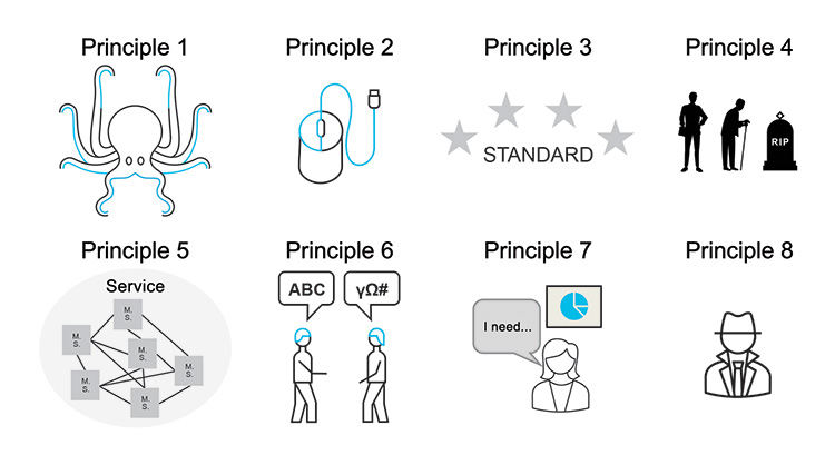
2.1 Principle 1 – Enable Flow of Data and Single Source of Truth
The Concept
The architecture is designed to facilitate the seamless FLOW OF DATA without creating multiple “instances” of information. This means that there is no need for multiple data stores housing different versions of the same information elements. Instead, there must be a strategy established where any application and/or machine can access a “single source of trustworthy data.” To achieve this, replication should be minimized whenever possible, and emphasis placed on ensuring that data is published and consumed as close as feasible to the data source.
The Why
Implementing this principle will help organizations comply with regulatory data integrity requirements. A general GMP requirement is: “You have to UNDERSTAND your processes to have it under control.” Therefore, “You have to UNDERSTAND the FLOW OF DATA (information flow) to have it under control.”
Under control means that you meet the requirements of ALCOA+:
A – Attributable
L – Legible
C – Contemporaneous
O – Original
A – Accurate
+ Complete, Consistent, Enduring, Available
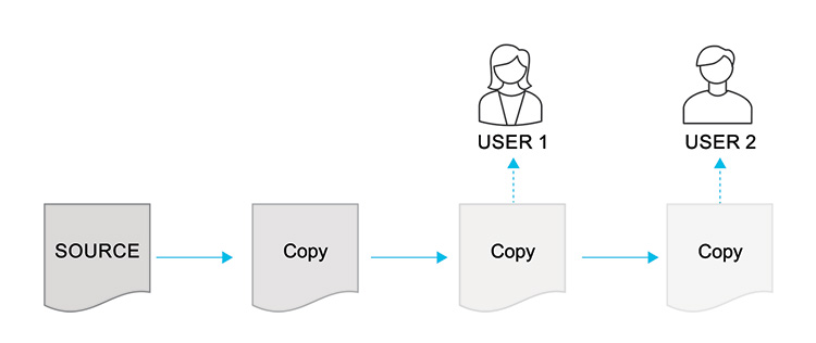
Information (data) should be accessible at its SOURCE from everywhere at any time within your facility. This applies to real-time/live data and historical data. Avoid saving a copy of a copy of a copy only for the purpose of sharing this information with different users as illustrated by Figure 2.2. The multiple copies are also likely to increase engineering and validation overhead.
Figure 2.2: Multiple Copies of Data
The Considerations
- How can all data sources/instances be available across the company vertically and horizontally – break data silos where data has limited access?
- Can Publish and Subscribe be supported?
- Can "Single Source of Truth” be applied for this application?
- What is the strategy to avoid data replication as much as possible?
- How is trustworthiness of data ensured within the architecture (considering all kinds of machines and IT-systems and the data they produce and consume)?
The Details and Examples
When looking for information (data), at least two questions must be considered:
- Can I trust this information?
- Is this the most current version of the information?
A good journalist would try to ask THE SOURCE to answer those questions and validate the data. If the SOURCE cannot be accessed, other platforms are trusted, such as newspapers, blogs, podcasts that publish information.
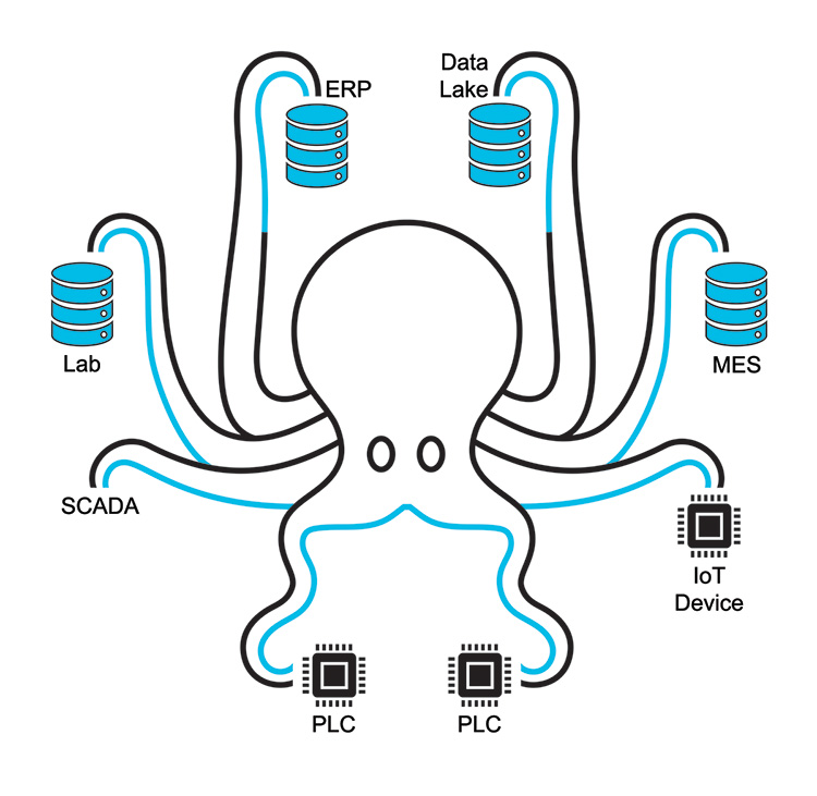
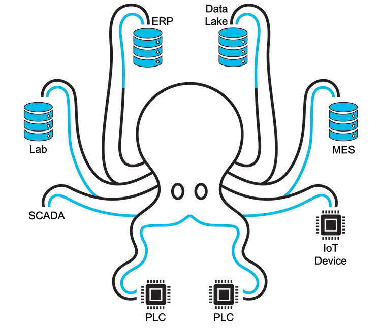
Most of the time information is gathered from different SOURCES to answer questions to take the right business decisions. This can lead to the demand of having a Single Source of Truth (SSOT) that the organization can trust. A SSOT gathers the requested information from different SOURCES on demand rather than storing it in one place. Imagine an octopus with its legs handling different elements of data as shown in Figure 2.3.
Figure 2.3: The “Single Source of Truth Octopus”
When considering information, you need to distinguish between:
- Real-time/live information
- Historical information
Whereas real-time/live information should be broadcasted by the source and so that any legitimate receiver can sign up for that information, historical information needs to be stored to receive it later. As mentioned earlier, historical information could be stored within the SOURCE of that data, but the complexity and security aspects need to be considered in order to decide on the data storage centralization/de-centralization approach.
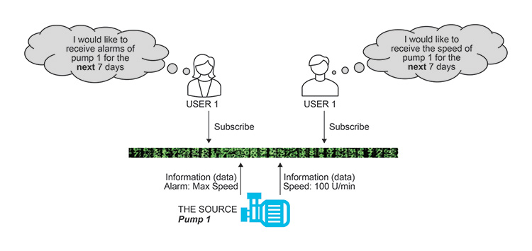
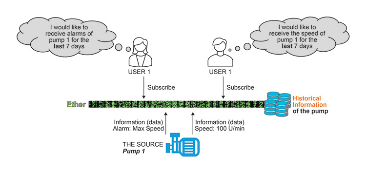
As an example, a pump could be THE SOURCE of information (data). To receive real-time/live information, users can subscribe to that pump per Figure 2.4.
Figure 2.4: Pump Live Information Receipt
The pump itself probably does not have data storage. Therefore, one concept could be to store historical information within the “ether.”
Figure 2.5: Pump Historical Information Receipt
The Typical As-Is Scenario
Hierarchical architectures are segregated into different levels of automation. Information must pass through different layers via a series of interfaces and transformations with granularity and content of data potentially being lost through layer transitions. For example, an historian may capture real-time process data through a compression algorithm and exclude the equipment audit trail; therefore, some of the data is transformed and some is lost.
Figure 2.6: System Architecture Model Evolution
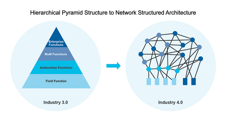
The Desirable To-be Scenario
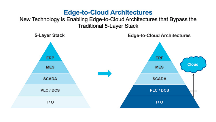
Efforts are made to limit data transformation and loss while minimizing multiple transitions of data. The goal is to share data directly from the source to reduce engineering and validation overhead for example, use of publish/subscribe technologies for data exchange.
Figure 2.7: Alternative “Straight to Source” System Architectures
2.2 Principle 2 – Enable Simplified Interface Configuration
The Concept
The architecture is designed to facilitate REPEATABLE, AUTOMATIC (Self) CONFIGURATION, aiming to reduce engineering and testing burdens. It moves away from “point to point” interfacing toward leveraging proven, standard, and automated integration of systems.
The Why/Purpose
One of the key objectives of the Plug & Produce concept is to provide interoperability between systems and equipment while minimizing effort cost, and risk while enhancing safety.
In the pharmaceutical industry, the VALIDATION of integration between equipment and systems constitutes a substantial portion of the overall costs and efforts. Typically, whenever a piece of equipment is connected to a system for the first time, a new interface is created, necessitating validation. This process is repeated even if the interface resembles that of another piece of equipment within the organization or has been used in a similar context elsewhere.
In ISPE GAMP® 5: A Risk-Based Approach to Compliant GxP Computerized Systems3 terms, many interfaces currently fall into Category 5 (bespoke) or at least Category 4 (configurable) requiring validation to ensure proper functioning and compliance. If these interfaces could be developed in a Category 3 (non-configured) or ultimately Category 1 (infrastructure) equivalent manner, the validation and configuration efforts would be significantly reduced.
The Considerations
- Does the architecture streamline validation efforts for both initial and subsequent integration activities?
- Does the architecture simplify engineering efforts for both initial and subsequent integration activities?
The Details and Examples
Consider the progression of the mouse as a computer peripheral.
- Initially, upon its introduction, there was no standardized method for integrating a mouse with a computer. Individuals had to manually write specialized programs for mouse functionality, which were not readily available to others.
- As computers evolved, manufactures began bundling the mouse with a separate driver. This driver was usually on removable media such as a disk that had to be installed and configured on the computer to enable mouse functionality.
- As computers evolved further, when the mouse was connected to the computer, it was automatically recognized, pre-installed standard drivers selected and the mouse would function with no setup required – the plug and play mouse had arrived!
Figure 2.8: The Bespoke Mouse Setup
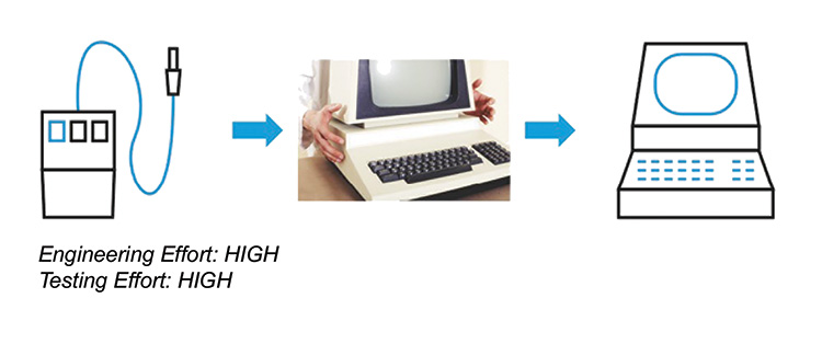
Figure 2.9: The Driver Mouse Setup

Figure 2.10: Mouse Setup Evolution
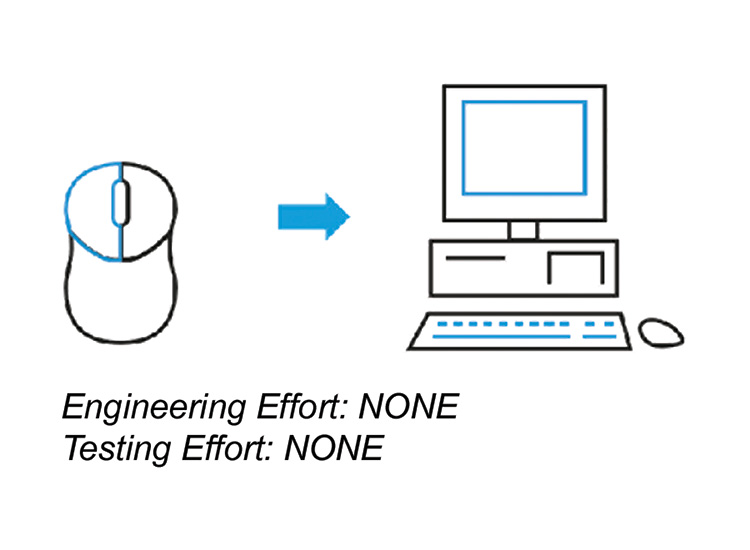
Applying that same evolution to pharmaceutical manufacturing, the aim in Plug & Produce is to achieve:
- Seamless integration between systems that takes place automatically, such as equipment integrating into a SCADA/DCS “automatically” without the need for programming; rather, it is achieved through automated configuration.
- Pre-tested integration by suppliers against a defined standard recognized by both integrating systems so that it integrates “out of the box.”
In practice this may not be possible due to either technical limitations or other organizational constraints such as cost or capability. Therefore, an intermediate solution, similar to Stage 2 in the mouse analogy, may be adopted to streamline engineering and validation efforts.
The Typical As-Is Scenario
Instances of “point” solutions, comparable to Stage 1 in the mouse analogy, are still widespread where bespoke and configured interfaces are implemented. Many organizations will be taking steps toward the ultimate goal through procedural approaches and the use of systems that enable organized control of replication.
The Desirable To-be Scenario
A true Plug & Produce architecture will support integration between systems ONLY by CONFIGURATION of INTERFACES rather than programming/engineering of INTERFACES. The most substantial business benefit will arise when achieving a fully automated configuration state comparable to the Stage 3 in the mouse analogy.
2.3 Principle 3 – Use Vendor Agnostic, Standards-based Approaches
The Concept
For many interfacing capabilities, there are both proprietary or limited use approaches and industry standard approaches. Embracing architectural approaches that are VENDOR AGNOSTIC and rely on EXISTING STANDARDS can yield significant benefits.
This approach avoids limiting capability to individual vendors and expands the range of options and possibilities as the architecture evolves.
The Why
To be able to implement the best services/functions from all existing solution providers to serve business needs effectively.
To be “open” for upcoming technology – to prevent vendor lock-in and broaden the range of options and possibilities as the architecture evolves.
The Considerations
- Is the architecture based on industrial standard approaches?
- How mature and widely utilized is the standard and consequently how limiting is the selection of technology?
- How to balance openness for the future against current standards?
The Details and Examples
EARLY adoption of technology always carries risks, as vendors may interpret and utilize standards in DIFFERENT ways in their unique vendor offerings.
For instance, in the 1970s, video players had two competing formats, Betamax and VHS, which were incompatible despite providing similar functions, that is, using a tape cassette they could both record and play video using a standard domestic TV set. While Betamax was considered in many ways to be a superior format, the uptake of VHS was at a much higher rate and eventually Betamax became unused by video manufacturers, meaning that those who had invested in this format needed to refresh their video library when they required a new player.
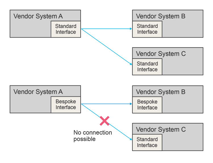
One way to mitigate this kind of risk to best align with options that are coming from industry standards rather than bespoke vendor approaches (even if the bespoke approach may be technically superior). Architectures that blend bespoke and standard interfaces risk losing the benefits of adopting a standard for part of the system, as illustrated in Figure 2.11.
Figure 2.11: Loss of Benefit of Standards
The Typical As-Is Scenario
There are a number of existing and emerging standards that will likely be applicable to a Plug & Produce architectural framework. These include but are not limited to OPC UA and Module Type Package (MTP).
The Desirable To-be Scenario
A full set of widely adopted standards will emerge and mature covering the entire architectural span for Plug & Produce capability. This will enable a more repeatable, comprehensive, standardized Plug & Produce architecture in the future.
2.4 Principle 4 – Enable Legacy System Integration
The Concept
The architecture accommodates and provides automatic mechanisms to connect LEGACY EQUIPMENT and LEGACY SYSTEMS with either “baked in” Plug & Produce compliant connectivity or without any implemented interface/data exchange standards.
The Why
At the point at which Plug & Produce capabilities become a reality, it is likely that the vast majority of pharmaceutical facilities will have equipment and systems that are unable to integrate in a Plug & Produce compliant manner. The value derived from PnP could be categorized into two main areas:
- Reduction in initial integration efforts
- Post-integration capability and functionality
As facilities move to Plug & Produce compliant architectures without a way to integrate legacy equipment, facilities will not be able to leverage this value.
The Considerations
- Can architecture be adopted to enable full or partial integration of legacy equipment and systems where value can still be gained?
- What is the “cut-off” point where effort of integration into a new architecture is still worthwhile compared to upgrading to compatible systems?
The Details and Examples
At the point in time when a greenfield facility is launched, it is already brownfield from a standards and technologies point of view. What is new today will soon become legacy as standards and approaches evolve, making it impractical to always have “new” systems.
Imagine if the workforce changed every time new technology emerged to a younger workforce! However, there may come a time when it is impractical to continue in a role – for instance, it is unlikely to see a 60-year-old professional footballer.
Figure 2.12: The Cycle of Life

Similarly, retirement of a system or piece of equipment is weighed based on various factors.
Two examples illustrate this:
a. Video Player Formats
In order to play a film collection on VHS, one needs to keep a VHS player. There are very few VHS machines available on the market today; therefore, replacing one may be more costly than investing in a modern format player like Blu-ray. Additionally, modern TVs may lack the necessary cable connections for the VHS player, requiring the use of adapters.
So, in order to maintain this VHS infrastructure until the films are worn out or they are no longer watched, someone could invest in a Blu-ray player and re-purchase (or convert) films into Blu-ray format. The Blu-ray player has modern connection types and can be plugged into a modern TV with a direct cable connection. The Blu-ray player also comes with enhanced features not available in VHS for a better movie-watching experience.
b. Healthcare Records
Many healthcare systems globally are transitioning from legacy paper-record systems to digital formats. However, until paper records are digitized, processes, procedures, physical storage, and archiving systems for managing the records must be maintained. This leads to operating both manual and digital systems concurrently until the transition is complete, as paper records remain critical for healthcare management.
The Typical As-Is Scenario
Currently, everything exists in legacy as a fully realized PnP world is not yet achieved. Within the legacy spectrum, equipment ranges from having no control system to possessing some capabilities used for PnP, such as OPC UA and MTP.
The Desirable To-Be Scenario
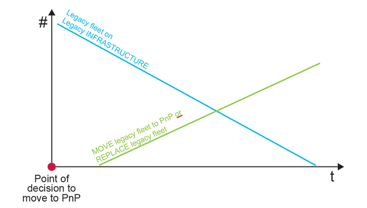
A PnP ready architecture includes a “translation” layer and standardized capabilities to integrate legacy systems. It is unlikely for Plug and Produce architecture to integrate every legacy item, necessitating a “cut-off” point for integration based on the level of legacy system support. This “cut-off” point, driven by various business factors including cost, must be established. For example, integration criteria could require support for at least OPC Classic or OPC UA.
Figure 2.13: Legacy Integration versus Legacy Replacement “Cut-Off” Point
2.5 Principle 5 – Use of Microservices
The Concept
Currently, many systems used for SCADA and MES rely on “monolithic” and hierarchical structures, where a single large application encompasses many standard features, many of which may go unused. To streamline integration and adopt a “use what you need” approach, the architecture should support microservices which are modularized aspects of functionality. AUTOMATIC identification of these (MICRO-)SERVICES and population from the EQUIPMENT/SYSTEMS would facilitate simplified integration.
The Why
- To enable a SERVICE-ORIENTED validation approach rather than a pure tag-based dataflow validation approach. Risk analysis is based on microservices.
- To differentiate between dataflow (information) and SERVICES (functions) provided by an asset. All microservices are populated by an asset.
- Reducing validation complexity is crucial for reducing validation cost.
The Considerations
- Can systems with microservices capabilities be utilized instead of a “monolithic” approach?
- Can requirement for individual microservices be automatically identified and utilized?
The Details and Examples
In pharmaceutical production sites, it is especially important to have the DATAFLOW under control, as discussed within PRINCIPLE 1. One could say that PRINCIPLE 5 acts an enabler for PRINCIPLE 1. Given the inherent complexity of dataflow, the approach is to modularize the entire picture into understandable, less-complex pieces.
For example, the ISA-88 models4 provide a framework for modularizing various aspects of a chemical process.
Figure 2.14: Modularization of a Process
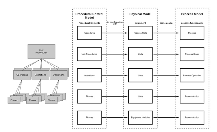
With this approach, CHEMICAL PROCESS LOGIC can be modularized. In this area of a pharmaceutical company, it is already common practice to validate “just” procedures, operations, phases and NOT the TAG-BASED DATAFLOW within that system.
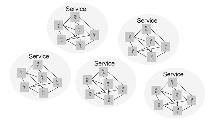
The concept of microservices is now to modularize SERVICES within the whole ENTERPRISE.
A micro-service is the smallest piece that can be described within a SERVICE-oriented ENTERPRISE architecture.
A micro-service always consists of 2 parts, BUSINESS LOGIC + DATAFLOW.
- Micro-service 1 + micro-service 2 + micro-service n = SERVICE
- Collection of all Services = Your Service-oriented architecture
Figure 2.15: Services Oriented Architecture
As an example, consider an automatic coffee machine. A user request from the machine (a user requirement) could be the following:
- Receive black coffee
To gain a bigger market share within the coffee machine industry, suppliers are adding more SERVICES to their coffee machines, which are then provided (populated) to the USERs. For example:
- Receive hot water
- Receive espresso
- Receive coffee with sugar
- Receive café crème
Figure 2.16: Coffee Machine “Services”
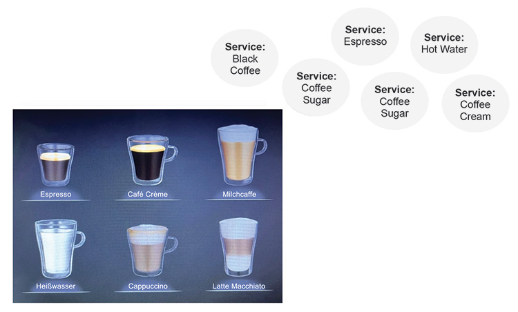
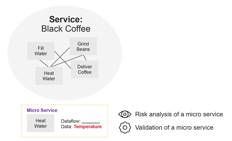
Not all services are required for all coffee types. In order to provide (populate) those SERVICES, the coffee machine will execute some internal FUNCTIONS/PROCESSES such as:
- Heating water (micro-service)
- Grinding beans (micro-service)
Those microservices generate information such as temperature, pressure, which may be of interest if coffee is being created under PHARMACEUTICAL REGULATORY REQUIREMENTS.
Figure 2.17: “Regulatory” Coffee
The Typical As-Is Scenario
There is no TRANSPARENCY (common knowledge) or understanding of implemented systems and services and their interdependencies.
Most often, there is no holistic strategy to modularize the ENTERPRISE ARCHITECTURE. Presence of large “monolithic” systems with unused features.
The Desirable To-Be Scenario
Establishment and understanding of what services are important (e.g., use of enterprise architecture roles). Building architecture around systems that are based on microservices.
Key message: FUNCTIONAL BREAKDOWN of your services can be supported by existing standards such as ISA-88/ISA-95;4, 5 this task has to be executed and documented within each company. It is important that the FUNCTIONAL BREAKDOWN is CONSISTENT and agreed upon by all parties/stakeholders/users. The biggest threat is the “discussion creep.”
2.6 Principle 6 – Support the Exchange of Data through Common Information Models
The Concept
Systems that exchange data can have many ways of “defining” and “describing” data.
Common information models can serve as the means to provide consistency of data definition to enable the exchange of data between systems.
The Why
It is likely that there will always be systems in the overall architecture that need to exchange data and will have the same data defined in different ways. They effectively speak a different language.
To provide effective and simplified communications, the “language” of data needs to be made common.
The Considerations
Is there a common “language” that can be standardized upon with the architecture?
Do you need to, and to what extent is it needed, introduce interpretation between systems?
The Details and Examples
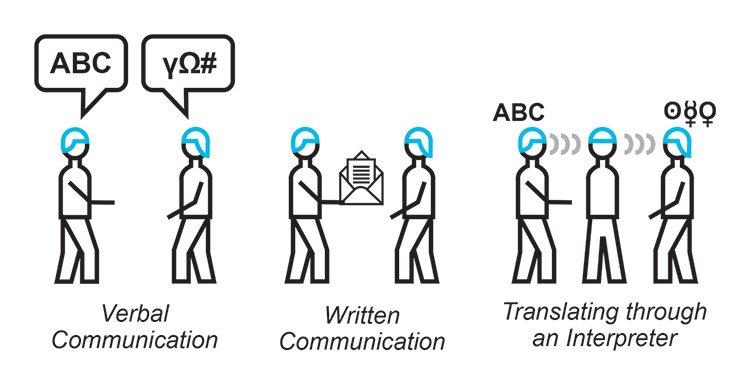
The interpretation of INFORMATION (data) is key. If two systems want to exchange information, this is no different than two persons speaking or two parties exchanging a letter. They have to speak the same LANGUAGE and know something about the grammar. If they do not, an INTERPRETER is needed who is HARMONIZING (TRANSLATING) the information before it arrives at the recipient. See Figure 2.18.
Figure 2.18: Information Exchange
For machines, it all starts within the CONTROLLER (PLC) (Figure 2.19).
Figure 2.19: Range of Programmable Logic Controllers (PLC) from Different Vendors

When discussing Level 2 to Level 3 integration, the focus is on the EXCHANGE of INFORMATION generated by controllers (PLCs), instruments, SCADAs, or other network-compatible systems within the production floor (Level 2).
An example is the EXCHANGE of so-called time series data, such as the speed of a pump. This SIGNAL, speed of a pump, “born” within a theoretical piping and instrumentation diagram, generated by a physical motor, received by the CONTROLLER (PLC), has to be named by ONE person, THE PLC PROGRAMMER.
The NAME of this SIGNAL within the PLC is called TAG.
Figure 2.20: Identifying a Tag in a PLC
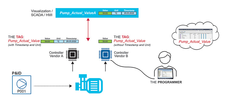
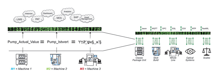
The TAG is as crucial as a person’s name to identify the information within the magnitude of data. To make this TAG detectable, it must be UNIQUE. To comply with this requirement, the PROGRAMMERS specify a NAMING CONVENTION that must be followed. Every equipment supplier has their own NAMING CONVENTION.
The PROBLEM STATEMENT illustrated in Figure 2.21 shows how Level 3 Systems receive different TAG-Names for the same signal type: speed of a pump.
Figure 2.21: BACNET Example
The Typical As-Is Scenario
Standards like BACnet®6 are trying to solve the PROBLEM at the core. SIGNALS, generated from devices that support BACnet, follow ALL the same NAMING CONVENTION specified by this STANDARD.
Figure 2.22: BACnet Naming Convention
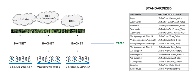
Therefore, it is NOT up to the PROGRAMMERS to specify their own NAMING CONVENTION. The standard is NOT applied to all system types – this standard is applied within the building automation sector. Within the Equipment-Process industry PACK ML is one example that could be used to specify TAGS among other attributes.
Figure 2.23: PackML Example
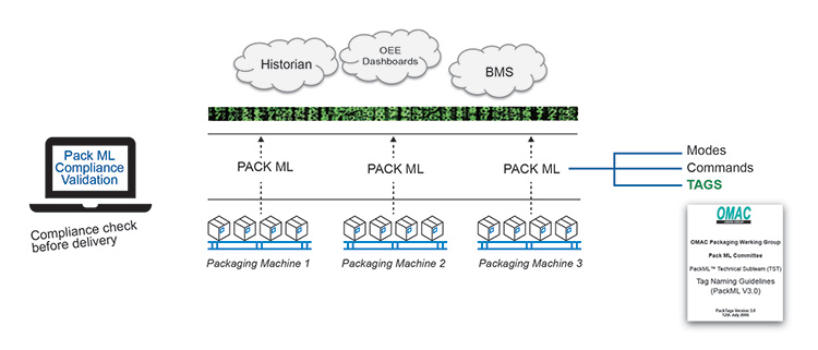
The PACK ML standard is mainly applied by suppliers of packaging machines. Furthermore, this standard uses the OPC UA technology, which provides the functionality to integrate INFORMATION MODELS (DATA MODELS). These INFORMATION MODELS are specified within so-called OPC UA Companion Specifications. And seen in Table 2.1, there are a lot more specifications to come.
| Industry Standard |
|---|
| OPC UA General Models (“Standard”) |
| OPC UA PackML Companion Specification |
| OPC UA Unified Architecture for AutomationML |
| OPC UA Unified Architecture for Robotics |
| OPC UA Unified Architecture for Machine Vision |
| OPC UA for Weighing Technology |
| OPC UA Unified Architecture for Analyzer Devices (ADI) |
| OPC UA for Pumps and Vacuum Pumps |
| OPC UA for Process Automation Devices |
| OPC UA for Compressed Air Systems |
| OPC UA for Machinery |
| OPC UA for Plastics and Rubber Machinery |
| ISA-95 Common Object Model |
| OPC UA Unified Architecture for Commercial Kitchen Equipment |
| OPC UA Unified Architecture for CNC Systems |
Another strategy is to use an INTERPRETER that TRANSLATES the INFORMATION. This INTERPRETER is often synonymous with middleware or IoT-platform.
Figure 2.24: Asset Administration Shell (AAS) Example
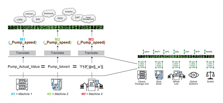
The Asset Administration Shell (AAS) concept picks up the problem statement and tries to realize interoperability with guidelines and specifications that assets can follow to fulfill that “standard.” The following definition is an abstract of the Asset Administration Shell Reading Guide:8
“The Asset Administration Shell (AAS) is the digital representation of an asset. The AAS consists of a number of submodels in which all the information and functionalities of a given asset – including its FEATURES, characteristics, properties, STATUSES, PARAMETERS, measurement DATA and CAPABILITIES – can be described.” (emphasis added)
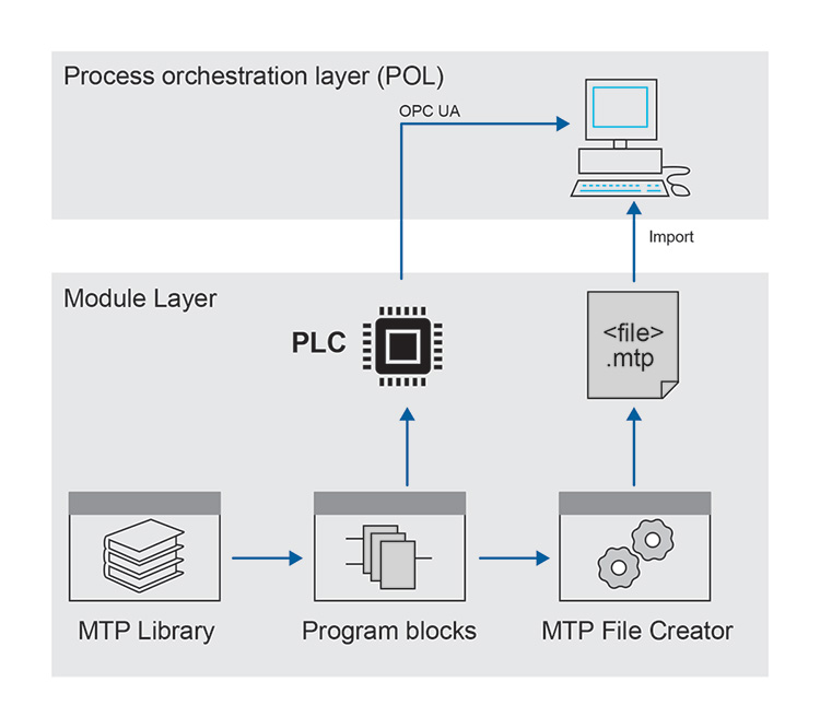
Another strategy is to send a SPECIFICATION up front to the RECEIVER so that the receiver can interpret the INFORMATION. The MTP concept supports that strategy.
Figure 2.25: Process Orchestration Layer (POL) Example
All the above-mentioned strategies to enable INTEROPERABILITY are less challenging when set up in a monolithic architecture. With a monolithic architecture (developed by one vendor) typically the different systems can “speak” to each other and share more or less the same information model by the means of a closed system.
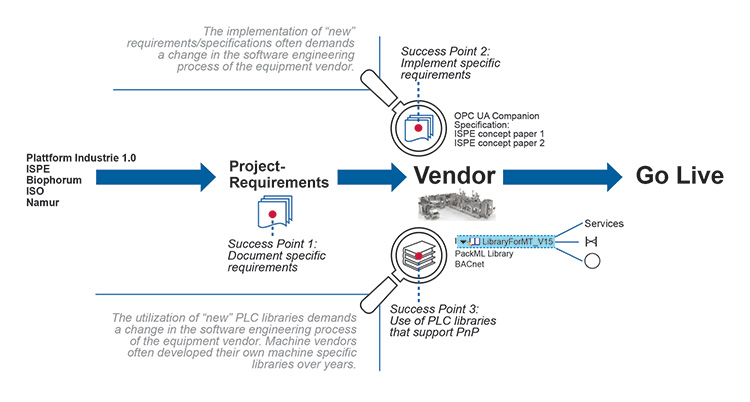
Since the LANDSCAPE of TAG-NAMING and INFORMATION MODELS is so fragmented it is evident that there will not be THE STANDARD. Therefore, it is still up to the suppliers to decide which specifications/guidelines and INFORMATION MODELS they follow:
Figure 2.26: Journey for Adoption of Common Information Models
The Desirable To-Be Scenario
SENDER and RECEIVER understand each other without any intervention from a human engineer. When the device is plugged-in, a full-blown process equipment is enabled or just a IoT device such as an intelligent sensor is enabled, which allows for all interested systems to discover the devices’ INFORMATION/DATA and available SERVICES.
2.7 Principle 7 – Provide Transparency, Visibility and Data Access
The Concept
To democratize data making it accessible to the masses rather than restricted to a select few. This is achieved by ensuring that data is transparent, visible, and accessible across as many systems as possible, rather than confined to a limited number of dedicated systems with limited capabilities.
The Why
To enhance decision-making processes. The more information individuals receive in a PERSONALIZED, understandable format, the better decisions they can make. TRANSPARENCY and VISIBILITY rely on accurate data presented in a relevant context.
The Considerations
Is data generated, stored, and processed in a manner that allows access to the appropriate systems capable of driving the necessary business decisions and actions?
Are data silos avoided to prevent the data from being “locked” away, thereby limiting its usability?
The Details and Examples
Imagine the SSOT octopus. The octopus has access to all the data and all that is needed is to ask.
Figure 2.27: “Single Source of Truth Octopus”
In a factory setting, vast amounts of information/data are generated, processed, and stored within numerous DATA SILOS spread across hundreds of databases. Operators, Quality personnel, business managers, engineers, and other employees require access to this information on a daily basis to make informed decisions. However, obtaining this information mostly comes from different data silos to ANSWER questions, such as:
- “What is the yield of the last batch?”
- “What is the average deviation of yield compared to the last thirty batches?”
- “What were the most common alarms for the last thirty batches?”
- “How much finished product can be produced with the actual raw material stock given a projected consumption and scrap rate?”
- “How much raw material has been lost due to scrapped batches in the last 6 months?”
Each role in a company, even each EMPLOYEE, has a personalized way of asking QUESTIONS and thus requires a PERSONALIZED approach to receiving information.
Figure 2.28: Organization Silos with Different Requests

The Typical As-Is Scenario
- Numerous data silos exist.
- There is no centralized “single point of contact” to access information (i.e., no Octopus with its single brain).
- Applications with limited user experience
- Lack of interfaces between systems
- Data may be “inaccurate,” neither contextualized nor normalized.
The Desirable To-Be Scenario
The right information is provided in the expected REPRESENTATION following the FAIR Guiding Principles for scientific data management and stewardship:
- Findable – Data sets should be easily discoverable for both humans and computers. Each asset is assigned a persistent identifier and metadata.
- Accessible – Once data is found, it should be readily accessible, with clear authorization processes in place. Common protocols, platforms, and access methods ensure data availability to the intended audience.
- Interoperable – Data should be easily combined with other data and compatible with standard applications. Standard terminologies, code sets, and exchange formats facilitate data sharing and utilization.
- Reusable – Data sets should be well-described to serve multiple purposes. Clear documentation of dataset provenance and any licensing requirements enables data reuse.
2.8 Principle 8 – Embed a High Level of Cyber Security
The Concept
In order to protect the data assets of an organization while leveraging their use, the architecture should support a standard approach to the OPEN EXCHANGE of information while ensuring a HIGH LEVEL OF SECURITY.
The Why
As IT and OT continue to converge, future state facilities must recognize that the end-to-end exchange of information is vital to digital operations while at the same time this information must be secured and protected from cyber threats.
As PnP architecture adoption moves away from monolithic systems to highly distributed, micro-service based architectures, there is a potential increase in cybersecurity risks, emphasizing the need to balance openness with robust security measures.
The Considerations
Is the level of cyber security aligned with the flow and accessibility of data to achieve business goals, considering the organization’s risk appetite?
Does the architecture introduce weak points that require reinforcement or replacement?
The Details and Examples
Consider a large secure storage area with a single-entry point and robust external walls and roof. Security efforts focus on fortifying the single-entry point to prevent unauthorized access.
If this single storage area is replaced by multiple interconnected smaller units, each with its own entry and exit points, securing the entire area becomes more complex. If one of the units has inferior security measures, it poses a risk to the overall structure.
Figure 2.29: Security of a Single Building versus Multiple Interconnecting Buildings
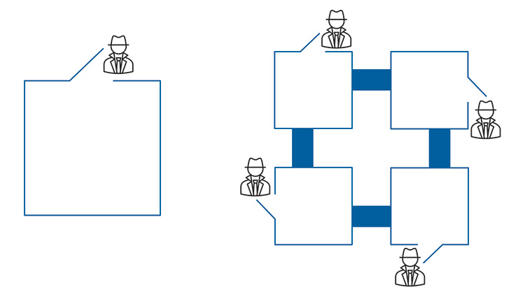
In a similar manner, transitioning from a “monolithic” system to multiple smaller systems increases the landscape for attack and not all systems may have equal cybersecurity measures in place.
The Typical As-Is Scenario
A monolithic system that has a fixed but secure architecture.
The Desirable To-Be Scenario
Provision of a secure, extensible architecture capable of cloud native integration to enable further service and scale opportunities. Ensure that users, applications, and devices, along with their interactions, are identifiable and known, enhancing visibility and enforcement capabilities.
Adherence to published standards such as IEC 624439 to provide a scalable, standardized approach to security compliance. Intrinsic inclusion of actor, application, and asset visibility along with associated traffic monitoring and enforcement mechanisms in the architecture.
Implement threat and vulnerability management across both IT and OT to provide a unified approach to risk management.
3 Incremental Move to PnP Architecture
The transition to a PnP capable architecture may require considerable investment and overcoming various obstacles. Adoption of new systems, incorporation of legacy investments, and building of capability are some of the many obstacles.
However, the PnP architecture principles discussed in this Concept Paper do not necessarily have to be adopted as a “big-bang” approach. Instead, there may be opportunities to adopt some of the principles outside of a fully compliant architecture and still obtain incremental benefit.
In other words, PnP architecture can be approached as an evolution rather than a revolution.
3.1 Equipment Integration
Consider Principle 2 – “Enable Simplified Interface Configuration” in the context of connecting to a SCADA/DCS system. The most substantial business benefit is achieved when using the fully automated configuration state given by a plug and play approach, as illustrated in Figure 3.1.
Figure 3.1: Simplified Equipment Integration Example
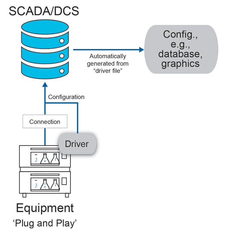
While achieving full automation may not be currently feasible due to various factors, incremental benefits can be realized through the adoption of technologies and architectures that enable partial implementation of repeatable configuration approaches. For instance:
1. Equipment Class models
The future may hold even more exciting developments with the use of AI technology, interfaces between equipment and systems could be automatically generated (rather than a manually composed interface template) based on the AI “understanding” of what tags within an equipment do and automatically mapping them into the connected system.
2. Class-Based Modeling
A class-based model is a description of the tags and characteristics of the equipment it is modeling. An equipment “class” can be generated based on the FUNCTION of the equipment (e.g., a tablet press) that is a COMMON MODEL for different manufacturers/models of the equipment, even if they are not identical, that share sufficient common characteristics to be considered of the same class. This “class” could have the following features:
- The output of the model (e.g., functions, tags) that is connected to a computerized system (e.g., a SCADA or DCS) is the same for all instances of the class.
- The input of the model (e.g., measured values from the equipment) may vary in terms of source and allows mapping to similar but not identical equipment.
The model allows different instances to be created for a series of tablet presses for example. In these instances, the inputs to the model need to be mapped to the different equipment. Because the output of the model does not change, once validated initially, only the inputs need to be configured and validated for subsequent instances, that is, the outputs and associated configuration of the model (database, graphics, alarms, etc) can be reused with no revalidation effort.
3.2 Evolution
A possible incremental progression route toward full achievement of the principle is:
- Manual replication processes (e.g., copy and paste) from templates or other similar examples to minimize errors in the engineering process.
- Validated manual replication processes (e.g., copy and paste) to reduce configuration and validation effort.
- Modeling to provide controlled replication processes (e.g., class-based modeling) to further reduce configuration and validation effort.
- Semiautomatic configuration using equipment drivers to generate pre-validated configurations (e.g., simplified equipment integration example above)
- Fully automatic configuration through automatic detection and utilization of equipment “drivers” during initial communication between equipment and systems.
Items 1, 2, and 3 will provide benefits after returns on initial higher investment (the first template needs to be created) by those performing the configuration.
Items 4 and 5 will not require templating by those performing the configuration and so if infrastructure is in place, will provide immediate benefits. They do, however, require investment into approaches by automation platform vendors and equipment manufacturers.
This incremental progression can be achieved by supplementing architectures and platforms with procedural approaches.
4 Validation and GAMP in a Plug and Produce Architecture
Interfacing of systems traditionally requires significant validation effort during implementation, with much of the burden falling on the implementor. For example, interfacing equipment with a historian often involves comprehensive testing of end-to-end mapping. In other words, GAMP risk-based approaches can be applied but in many cases it is difficult to justify not performing a complete test of end-to-end mapping of all tags from the equipment to the historian, particularly if the mapping process relies heavily on manual-type activities.
Moving toward a Plug and Produce architecture, two aspects of validation can undergo transformation:
- By eliminating manual activities from integration, the risk of errors is reduced, leading to decreased validation efforts.
- The validation focus shifts from in-situ integration activities to up-front development work by equipment and system vendors. Similar to the plug and play mouse analogy, mouse manufacturers develop and test drivers to minimize integration issues for users.
However, convincing OEM equipment manufacturers to invest up-front in developing plug and produce integration capability may pose initial challenges, as the benefits primarily accrue to end users.
In GAMP terms, the objective of the architecture is to transition from interfacing of systems from GAMP Category 5 (custom or bespoke) to GAMP Category 3 (non-configurable) or even Category 1 (infrastructure). Successful implementation of AI for automatic system integration may necessitate adopting new validation approaches and applying “critical thinking.”10
5 Conclusion and Outlook
Figure 5.1: A New Architectural Approach
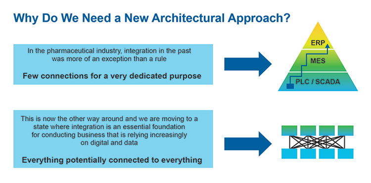
One goal is to move away from the idea of having a “golden” architecture and instead focus on adopting architectural principles tailored to individual circumstances and legacy architecture. Given the ongoing maturation of technology and standards in the Industry 4.0 space, it may be premature to establish a definite approach.
Alternatively, embrace architectural principles rather than specific systems. These principles underpin the benefit goals and mitigate potential pitfalls including but not limited to data integrity and cybersecurity.
Look to minimize up-front “big-bang” investment and maximize returns by incremental progression toward principles where the biggest benefits can be identified. Remain updated with emerging technologies and evolving standards in the Pharma 4.0 landscape to leverage the full potential of PnP architecture.
6 Annex – Related Standards
| # | Industry Standard | Comment |
|---|---|---|
| 1 | ISA RAMI 4.011 | The RAMI 4.0 Reference Architectural Model for Industry 4.0 components give companies a framework for developing future products and business models. |
| 2 | NAMUR Module Type Package – MTP12 | Modular automation of process modules (e.g., Package Units) can be realized through the usage of so called Module Type Packages (MTP) in order to increase the flexibility of the production. |
| 3 | Asset Administration Shell – AAS | The AAS is the digital representation of an asset. The AAS consists of a number of submodels in which all the information and functionalities of a given asset – including its features, characteristics, properties, statuses, parameters, measurement data, and capabilities – can be described. Part 1: Details of the Asset Administration Shell – The exchange of information between partners in the value chain of Industrie 4.013 Part 2: Details of the Asset Administration Shell Interoperability at Runtime – Exchanging Information via Application Programming Interfaces14 |
| 4 | OPC Unified Architecture (OPC UA) – Part 5: Information Model15 | IEC 62541-516 OPC UA is a cross-platform, open-source, IEC62541 standard for data exchange from sensors to cloud applications developed by the OPC Foundation |
| 5 | ISA-95 Common Object Model 5 | ISA-95 provides a standard manner to describe the flow of information between Manufacturing Operations Management (MOM) |
| 6 | PackML Machine Control and Automation Standard17 | PackML is an automation standard developed by the OMAC and adopted by ISA as TR88.00.0218 that makes it easier to transfer and retrieve consistent machine data. The primary goals of PackML are to encourage a common “look and feel” across a plant floor, and to enable and encourage industry innovation. |
| 7 | IEC 61499 Standard for distributed Automation19 | The IEC 61499 architecture represents a component solution for distributed industrial automation systems aiming at portability, reusability interoperability, reconfiguration of distributed applications. |
| 8 | BACnet communication protocol6 | BACnet has been designed specifically to meet the communication needs of building automation and control systems. The BACnet protocol provides mechanisms by which computerized equipment of arbitrary function may exchange information, regardless of the particular building service it performs. |
7 Acronyms and Abbreviations
| AAS | Asset Administration Shell |
| AI | Artificial Intelligence |
| DCS | Distributed Control System |
| GMP | Good Manufacturing Practice |
| IoT | Internet of Things |
| IIoT | Industrial Internet of Things |
| IT | Information Technology |
| MES | Manufacturing Execution System |
| MTP | Modul Type Package |
| NAMUR | Normenarbeitsgemeinschaft für Mess- und Regeltechnik in der Chemischen Industrie |
| OEM | Original Equipment Manufacturer |
| OMAC | Organization for Machine Automation and Control |
| OPC UA | Open Platform Communications Unified Architecture |
| OT | Operational Technology |
| PLC | Programmable Logic Controller |
| PnP | Plug and Produce |
| POL | Process Orchestration Layer |
| RAMI | Reference Architecture Model for Industrie 4.0 |
| SCADA | Supervisory Control and Data Acquisition |
| SSOT | Single Source of Truth |
Limitation of Liability
In no event shall ISPE or any of its affiliates, or the officers, directors, employees, members, or agents of each of them, or the authors, be liable for any damages of any kind, including without limitation any special, incidental, indirect, or consequential damages, whether or not advised of the possibility of such damages, and on any theory of liability whatsoever, arising out of or in connection with the use of this information.
© Copyright ISPE 2024. All rights reserved.
All rights reserved. No part of this document may be reproduced or copied in any form or by any means – graphic, electronic, or mechanical, including photocopying, taping, or information storage and retrieval systems – without written permission of ISPE.
All trademarks used are acknowledged.
Acknowledgements
This Concept Paper represents the outcome of work done by the members of ISPE Pharma 4.0 Plug & Produce Working Group as well as experiences and input from the individuals listed and does not reflect the views of any one individual or company.
Document Authors
Anton Granget Faktory Labs Germany
Kim Hewson GSK United Kingdom
Christian Miguel-Langstrof Pharmaplan Germany
Contributors
David McKee IPS USA
Sandra Donato Silva ValGenesis Portugal
Marc Wallis AstraZeneca United Kingdom


