Process Events for the Life Science Industry - Information Model Concept on OPC UA for Alarms and Audit Trails

This Concept Paper proves that a standard model within OPC UA Alarms and Conditions (OPC UA Part 9) can be leveraged to realize Plug & Produce for exchanging pharmaceutical alarms and audit trails between OT manufacturing equipment and Orchestration Platforms or IT Services like EBR or Historian.
Abstract
Plug & play in general describes a piece of equipment that is ready to use upon connecting to a computer without any configuration, like a home printer. Plug & Produce has the same vision for manufacturing and aims to enable straightforward integration of new production equipment or a device to substitute or adapt assembly line parts.
Concepts like OPC UA and Modular Type Package (MTP) are the groundwork for the standardization of interfaces and data formats for shop floor manufacturing equipment to enable Plug & Produce. However, current standards focus either on technical integration concepts or information structures. To fully realize Plug & Produce, technical integration, information structure, and biopharmaceutical-specific elements and documentation need to be in place.
This Concept Paper proves that a standard model within OPC UA Alarms and Conditions (OPC UA Part 9) can be leveraged to realize Plug & Produce for exchanging pharmaceutical alarms and audit trails between OT manufacturing equipment and Orchestration Platforms or IT Services like EBR or Historian.
Discussion of proprietary technologies is included to convey practical information to the readers. In no way does this Concept Paper endorse or promote the use of these items.
1 Introduction
In life science industries, GMP relevant alarms and audit trail events that occur during production must be reviewed as part of the batch release process. However, industrial standards lack the mechanisms and information model to support this critical part of the process in a way that can be adopted by equipment manufacturers and software suppliers.
This Concept Paper provides an overview of the typical landscape of life sciences systems along with challenges faced today when passing information related to events such as alarms and audit trails between systems and equipment. It describes new elements proposed for the OPC UA specification offered by this group that could be a step toward remediating these challenges. Without improvement, equipment vendors and their customers must expend additional effort to ensure compliance with regulations.
In this first release of this draft specification focused on events, “Alarms” and “Audit Trail” are the initial areas defined. To capture the life science industry specific requirements, the ISPE Pharma 4.0 Plug & Produce team reviewed work products from industry organizations such as BioPhorum 1, 2, NAMUR 3, and life science companies, and merged elements of those work products with what is already provisioned for in the OPC UA specification.
This document connects to the previous work done by the ISPE Pharma 4.0 Plug & Produce working group, described in “Connectivity between Shopfloor and Manufacturing Operations Management Systems with OPC UA - A Tangible Step Toward Plug & Produce.” 4 This Concept Paper describes an approach for transactional communication between shopfloor and IT systems using the OPC UA standard and in particular “OPC UA Methods.”
This current Concept Paper also refers to documents released by BioPhorum such as: “Plug-And-Play Audit Trail Requirements”1 and “Stirred Tank Unit Interface Specification” 2.
2 Data Integration between Shopfloor and IT Systems: Current Status
Before delving into the specifics of what is being proposed, it is useful to review the current state of technology, and how equipment vendors, system suppliers, and their customers must adapt to meet regulatory demands with existing technical limitations.
2.1 Typical Use Case: Integration between Production Equipment and an Electronic Batch Record or Historian
Communication between shopfloor and manufacturing IT systems can be divided into three communication channels, as shown in Figure 2.1 and further described in Sections 2.1.1 – 2.1.3.
Figure 2.1: Communication Channels
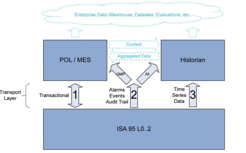
2.1.1 Transactional Communication (Channel 1)
Communication between the Manufacturing Execution System (MES) and the shopfloor is characterized by the bidirectional and transactional communication of data sets. These are often planned and part of the programming/recipe on both levels. Typically, all data exchanged is GMP relevant. The most common transactions to support some use cases are listed in the following paragraphs.
2.1.1.1 Batch/Lot Parameter Data Exchange
MES to Shopfloor: Sending of data at batch setup to prevent potential transcription errors.
Example: Product/Recipe: xx*, Batch: xx, Param1: xx, Param2: xx Param3: xx
*Assumes that equipment contains a validated recipe. Recipe selection and any variable data must be mapped to relevant tags.
2.1.1.2 In-Process Controls
Trigger the taking of a sample during production, controlling it, and recording In-Process Control (IPC) results.
Example: Checkweigher “spotcheck” can be triggered via OPC, which results in a number of weights being captured.
2.1.1.3 Batch Result
At the end of the batch, information has to be sent to MES providing the production result. This could be merely “OK,” “Not OK,” or more expansive based on requirements. It could include key results from equipment or historian.
2.1.2 Alarms, Events, Audit Trail (Channel 2)
2.1.2.1 Alarm and GMP Exceptions
Characterized by event driven, unplanned or only partially planned, and unidirectional communication, these typically include GMP and non-GMP alarms. An alarm can be considered as a stateful event as it can have different statuses (Alarm generated, Alarm is acknowledge by a user, Alarm cleared).
2.1.2.2 Audit Trail
Characterized by event driven, unplanned or only partially planned, and unidirectional communication, these typically include GMP-relevant events.
2.1.3 Time Series Data (Channel 3)
2.1.3.1 Process Values as Time Series
Typically, sensor or counter values are recorded at defined intervals into an historian or similar system specifically designed to work with larger data volumes of time/value data pairs. This can be GMP relevant, such as Critical Process Parameters (CPP), and non-GMP data, for example, data used for process optimization or as Key Performance Indicators (KPIs).
2.2 Classical Approaches
A classic approach for integrating data from machinery and production lines is the adoption of centralized process historian systems.
The historian stores data acquired from field devices, reading process variables (i.e., “Tags”). In addition, the historian can connect to the MES system via proprietary interfaces. This hierarchical approach, briefly illustrated in Figure 2.2, shows certain limitations.
Figure 2.2: ISA 95 Levels (Classic Hierarchical Integration)
.png)
By connecting to the machine PLC (Programmable Logic Controller) or SCADA (Supervisory Control and Data Acquisition), the historian is able to read process variables in real time. This solution is well suited for storing time-series values (e.g., a temperature trend).
However, when it comes to collecting alarm signals, such as critical GMP exceptions, the matter becomes a little more complicated. First, the alarm condition generated in the machine must be recreated in the historian. However, the historian cannot understand the complete alarm lifecycle, for example, when the alarm was acknowledged at the machine level and by whom. This metadata is not normally available as process variables.
The issue becomes even more complex when dealing with audit trail messages. How can a “value change event” of a critical GMP parameter including any electronic signatures entered by operators be captured? As of today, there is no standardized approach to the integration of alarms and the audit trail that includes metadata required for data integrity compliance. Today, audit trail integration is mainly based on file import/export (CSV or XML files), possibly using a different customized approach from machine to machine, increasing integration costs and complexity for pharmaceutical companies.
Furthermore, like all IT systems, MES systems are not designed to exchange values in real time with SCADA and PLC. As stated, communication between the MES and shopfloor takes place in a transactional manner by exchanging messages in a specific moment. The handshake between “Tag-based communication” and transactional communication is one example of the limitations.
2.3 Some Examples of Modern Approaches
2.3.1 NAMUR MTP Concept
NAMUR 5, an international association of user companies in the process industry for automation technology, together with German association ZVEI 6, support a plug-and-play approach by defining a Module Type Package (MTP) concept (VDI/VDE/NAMUR 26587). The model allows for more flexibility when considering modular automation by enabling the quick assembly and disassembly of systems from different vendors in the architecture.
The basic requirement for consistent modularization in production is a uniform description of the information about the individual modules. Which data objects are present? Which services are to be executed?
“Requirements for Process orchestration of modular production plants” NE187 3 provides details on the overall concept, which is summarized here.
According to MTP terminology, a module such as a bioreactor, a filter, or a skid is called a Process Equipment Assembly (PEA).
Each PEA presents its integration capabilities, such as the services it can offer (e.g., a reactor will offer a filling or stirring service), configuration parameters, alarms, and Human-Machine Interface (HMI) objects. All this information is described in an Automation Markup Language (AML) file.
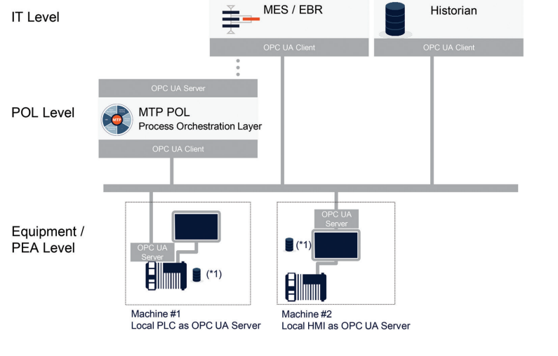
All PEAs provide information in a standardized format independent from the control system they have, facilitating integration into a superordinate Process Orchestration Layer (POL), as seen in Figure 2.3.
Figure 2.3: POL to PEA 8
![Figure 2.3: POL to PEA [8]](https://ispe.org/sites/default/files/concept-papers/Information%20Model%20Concept%20on%20OPC%20UA%20for%20Alarms%20and%20Audit%20Trails/Figure%202.3%20POL%20to%20PEA%20%5B8%5D.png?s111037d1716328468)
The development of MTP continues and while it represents a very promising approach that will drive standardization in industry, the standard is incomplete for usage within the life science industry, particularly alarms, events, and audit trail management. Furthermore, vendors must adopt the use of OPC UA, and any new processes introduced may require certification.
2.3.2 Message-based Shopfloor Integration
Replacing tag-based exchanges of data with structured message-based communications simplifies the integration and support of MES/POL to Shopfloor system communications. This type of integration requires implementation of additional capabilities by the equipment vendor upfront, but enables earlier integration testing and business-readable messaging. For example, integration implemented via tag exchange requires specifications to define multiple data elements to be exchanged and how handshaking occurs, and these designs vary by vendor/equipment type. By comparison, a message-based protocol provides a business-readable structure that can provide for early integration and for ease of troubleshooting in the event there is a problem.
In 2019, a group of equipment vendors, software providers, and life science companies came together for a Hackathon to explore technological approaches of MES/POL to Shopfloor integration. The group explored a number of technologies including OPC UA, MTP, and vendor-specific offerings to realize the aspiration of “Plug and Produce.”
Following the Hackathon, a team of ISPE members was formed to produce a Concept Paper largely based on learnings from the Hackathon titled “Connectivity between Shopfloor and Manufacturing Operations Management Systems with OPC UA – A Tangible Step Toward Plug & Produce,” [4] as OPC UA methods was agreed to be the most sensible option to progress.
The message-based approaches support bidirectional communication, and have been implemented using technologies such as OPC UA Methods and Web Services. It supports transactional communication typically requested at the start of a batch or at the end of a batch. At the same time it supports exception handling throughout the batch. For example, a piece of shopfloor equipment can send to MES GMP-relevant alarms or exceptions in real time or at the end of batch.
For greenfield installations, implementation of a message-based communication approach can be a challenge to vendors whose current solutions are created on tag-based communications. In brownfield scenarios legacy equipment and protocols will introduce even more complex architectures.
3 Suggested ISPE Approach
3.1 Introduction to OPC Unified Architecture (OPC UA)
OPC UA 9 is an open and royalty free set of standards designed as a universal communication protocol. While there are numerous communication solutions available, OPC UA has key advantages:
- A state of the art security model (see OPC 10000-2) 10)
- A fault-tolerant communication protocol
- An information modeling framework that allows application developers to represent their data in a way that makes sense to them
OPC UA has a broad scope that delivers economies of scale for application developers. This means that a larger number of high-quality applications at a reasonable cost are available. When combined with semantic models such as PROFINET 11 (https://www.profinet.com/profinet-explained), OPC UA makes it easier for end users to access data via generic commercial applications.
The OPC UA model is scalable from small devices to Enterprise Resource Planning (ERP) systems. OPC UA Servers process information locally and then provide that data in a consistent format to any application requesting data, for example, ERP, MES, production management systems, maintenance systems, HMI, smartphones, or a standard browser. For a more complete overview see OPC-10000-1 10.
As an open standard, OPC UA is based on standard internet technologies, such as TCP/IP, HTTP, and web sockets.
As an extensible standard, OPC UA provides a set of Services (see OPC-10000-1 10) and a basic information model framework. This framework provides an easy manner for creating and exposing vendor-defined information in a standard way. More importantly all OPC UA Clients are expected to be able to discover and use vendor-defined information. This means OPC UA users can benefit from the economies of scale that come with generic visualization and historian applications. This specification is an example of an OPC UA Information Model designed to meet the needs of developers and users.
3.2 Transactional Communication Based on OPC UA Methods
The ISPE Concept Paper “Connectivity between Shopfloor and Manufacturing Operations Management Systems with OPC UA – A Tangible Step Toward Plug & Produce” 4 proposes an approach for transactional communication based on OPC UA methods.
3.3 Alarm and Audit Trail Exchange Based on OPC UA Events
The OPC UA standard supports “Alarms” and “Events,” also referred to as “Alarms” and “Conditions.” OPC 10000-9 10However, there are gaps in the data these standards provide, in particular for life sciences companies. A common example is “Criticality,” which defines whether or not a particular event could impact product quality, or have an environmental, health, or safety impact. Another example is the additional metadata required for audit trail entries where GxP regulations require these events to be attributed to a user.
The authors believe the support of “Alarms” and “Conditions” within the existing standard is a good starting point, and further recognize that the OPC standard provides several good mechanisms whereby the specification can be enhanced to support the requirements of life science companies.
Using this functionality available in OPC UA, there is no longer the need for a complex configuration of the higher-level IT service to integrate alarms and audit trails. Simply subscribe to the alarm or event notification service provided in the OPC server of the machine. As soon as the event is generated, it will be automatically sent to the connected client with all the required metadata. In the case of an accidental disconnection, there is a “history read” method built into the OPC server through which any lost events can be recovered. As a consequence, it must be considered that the device integrating this functionality must have an event buffering system for a sufficient period of time to cover any communication interruptions.
To clearly describe where these data objects are applicable within a manufacturing system’s landscape, it is useful to describe the different “levels” of equipment in terms the reader can identify with. In Figure 3.1, the physical plant model defined within NAMUR NE-187 3 is presented.
Within this proposal for parameters to be added in support of life sciences, some aspects such as batch information or criticality may not be available in the lowest layers of this model. However, designs must consider that these aspects must be available at upper levels. As an example, a scale may pass an alarm, but whether that alarm is critical to the current product in production is unknown and therefore is set to “0-Unclassified.” Without modification, the MES/POL must consider this alarm as “Critical.”
Figure 3.1: Definition of PEA Types 3
![Figure 3.1: Definition of PEA Types [3]](/sites/default/files/concept-papers/Information%20Model%20Concept%20on%20OPC%20UA%20for%20Alarms%20and%20Audit%20Trails/Figure%203.1%20Definition%20of%20PEA%20Types%20%5B3%5D.png)
3.3.1 Advantages of OPC UA Events and OPC UA Alarms and Conditions
OPC UA Events and OPC UA Alarms and Conditions offer these advantages:
- Subscribe to events
- History read (in case of communication loss)
- No import/export of files
- Online communication based on an industry standard
- Robust contextualized dataset exchange
- Atomic data delivery
3.3.2 Challenges of OPC UA Events and OPC UA Alarms and Conditions
The challenges presented by OPC UA Events and OPC UA Alarms and Conditions are:
- To enhance reliability of communications OPC UA server should support History Read, therefore a local short-term data buffer will be required
- Not all vendors (equipment and software) support Events
3.3.3 Example OPC UA Alarms and Conditions based Architecture
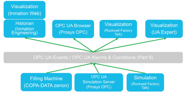
Figure 3.2 represents a high level architecture where a machine containing an OPC UA Server distributes alarms and events simultaneously to multiple clients. Some key points:
- POL, MES, and Historian receive Alarms and Audit Trail Events from equipment acting as OPC UA Clients.
- Each OPC Client subscribes to PharmaAlarmType (described in Section 3.4.1) and PharmaAuditTrailEvent (described in Section 3.4.2) event notifiers, or can retrieve all events via a History Read Request
- Machines must support OPC UA Alarm and Condition. Alarms and AuditTrail events are sent by the PharmaAlarmType and PharmaAuditTrailEventType event notifiers respectively.
- PLC or local SCADA “must” have a local event short-term buffer supporting “History Read” to prevent the loss of data in the event of a disconnect.
Figure 3.2: Example Architecture Employing OPC UA Alarm and Conditions
3.4 Event Types Definitions
3.4.1 PharmaAlarmType
Figure 3.3: PharmaAlarmType within OPC UA Event Type Hierarchy
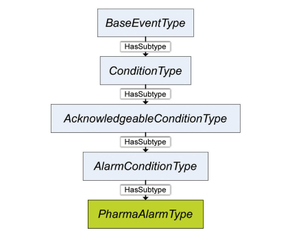
PharmaAlarmType is derived from AlarmConditionType defined in OPC-10000-910. Refer to that specification regarding the specifics as to when an event is fired when alarm state changes occur. PharmaAlarmType is formally defined in Table 3.1. For a complete list of attributes, including those inherited from the base type, see Table 6.2.
| Attribute | Value | ||||
|---|---|---|---|---|---|
| BrowseName | PharmaAlarmType | ||||
| References | NodeClass | BrowseName | DataType | TypeDefinition | ModelingRule |
| Subtype of AlarmConditionType defined in OPC-10000-9 10. | |||||
| HasProperty | Variable | AlarmCategory | AlarmCategory | PropertyType | Mandatory |
| HasProperty | Variable | AlarmId | Sintrg | PropertyType | Mandatory |
| HasProperty | Variable | BatchInformation | BatchInformation | PropertyType | Optional |
| HasProperty | Variable | Criticality | Criticality | PropertyType | Mandatory |
| HasProperty | Variable | Entity | Sintrg | PropertyType | Mandatory |
| HasProperty | Variable | EquipmentId | Sintrg | PropertyType | Mandatory |
| HasProperty | Variable | Location | Sintrg | PropertyType | Optional |
| HasProperty | Variable | MessageDefaultLanguage | Sintrg | PropertyType | Optional |
| HasProperty | Variable | Operator | Sintrg | PropertyType | Mandatory |
| HasProperty | Variable | OperatorName | Sintrg | PropertyType | Optional |
AlarmCategory defines the category of this alarm. See Section 3.4.4 for the definition of the AlarmCategory data type.
AlarmId is an equipment-specific identifier of the alarm. It is assumed that this identifier is documented in the documentation of the equipment.
BatchInformation provides batch context for this alarm. See Section 3.4.5 for the definition of the BatchInformation data type.
Criticality defines the criticality of this alarm. See Section 3.4.3 for the definition of the Criticality data type.
Entity is the object that is the source of the alarm.
EquipmentId is a unique identifier, identifying the equipment within a corporation owning or using the machine or within a site.
Location describes the physical location of the equipment as equipment can be mobile.
MessageDefaultLanguage contains the Message from the BaseEventType translated into the default language.
Operator is the unique identifier of the operator acting on the alarm. In some cases, this could be a “system” identifier.
OperatorName name of the operator acting on the alarm.
Note that basic information such as timestamps are defined in BaseEventType (defined in OPC-10000-5 10).
The BaseEventType defines a variable “Severity” of type UINT16 with a range of 1-1000. Not every system vendor uses this range to depict their severity. This type assumes that a mapping of each system’s native severity range is done to the OPC UA standard range. For the purpose of this alarm type it is suggested that severities are distributed across the scale as depicted in Section 6.4.2 of OPC 10000-5: UA Part 5: Information Model10.
3.4.2 PharmaAuditTrailEventType
Figure 3.4: PharmaAuditTrailEventType within OPC UA Event Type Hierarchy
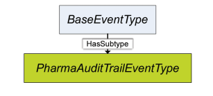
PharmaAuditTrailEventType is derived from BaseEventType (defined in OPC-10000-5 10). A PharmaAuditTrailEvent is fired whenever an action relevant to the audit trail occurs. PharmaAuditTrailEventType is formally defined in Table 3.2. For a complete list of attributes, including those inherited from the base type, see Table 6.1.
| Attriebut | Value | ||||
|---|---|---|---|---|---|
| BrowseName | PharmaAuditTrailEventType | ||||
| References | NodeClass | BrowseName | DataType | TypeDefinition | ModelingRule |
| Subtype of BaseEventType defined in OPC-10000-1 10. | |||||
| HasProperty | Variable | Action | Action | PropertyType | Mandatory |
| HasProperty | Variable | Agent | String | PropertyType | Optional |
| HasProperty | Variable | BatchInformation | BatchInformation | PropertyType | Optional |
| HasProperty | Variable | Criticality | Criticality | PropertyType | Mandatory |
| HasProperty | Variable | Entity | String | PropertyType | Optional |
| HasProperty | Variable | EntityClass | String | PropertyType | Optional |
| HasProperty | Variable | EquipmentId | String | PropertyType | Optional |
| HasProperty | Variable | Location | String | PropertyType | Optional |
| HasProperty | Variable | MessageDefaultLanguage | String | PropertyType | Optional |
| HasProperty | Variable | NewValue | BaseDataType | PropertyType | Optional |
| Attribute | Value | ||||
|---|---|---|---|---|---|
| BrowseName | PharmaAuditTrailEventType | ||||
| References | NodeClass | BrowseName | DataType | TypeDefinition | ModelingRule |
| Subtype of BaseEventType defined in OPC-10000-1 10. | |||||
| HasProperty | Variable | OldValue | BaseEventType | PropertyType | Optional |
| HasProperty | Variable | Operator | String | PropertyType | Mandatory |
| HasProperty | Variable | OperatorName | String | PropertyType | Optional |
| HasProperty | Variable | Reason | String | PropertyType | Optional |
| HasProperty | Variable | UnitOfMeasure | String | PropertyType | Optional |
Action describes the type of event that has occurred from the Action enumeration
Agent describes the source of the event (e.g. user, system generated)
BatchInformation provides an optional batch context for this audit trail event. See Section 3.4.5 for the definition of the BatchInformation data type.
Criticality defines the criticality of this audit trail event. See Section 3.4.3 for the definition of the Criticality data type.
Entity describes the object relevant to this audit trail event.
EntityClass describes the type of object relevant to this audit trail event (e.g., setpoint, security rights).
EquipmentId is a unique identifier, identifying the equipment within a corporation owning or using the machine or within a site.
Location describes the physical location of the equipment as equipment can be mobile.
MessageDefaultLanguage contains the Message from the BaseEventType translated into the default language.
NewValue contains the current value of the entity.
OldValue contains the value of the entity prior to the event that triggered this audit trail event.
Operator contains the unique identifier of the operator triggering the event.
OperatorName contains the name of the operator triggering the event.
Reason contains the operator entered reason given for the action causing the audit trail event.
The BaseEventType defines a variable “Severity” of type UINT16 with a range of 1-1000. Not every system vendor uses this range to depict their severity. This type assumes a mapping of each system’s native severity range is done to the OPC UA standard range. For the purposes of this alarm type it is suggested that severities are distributed across the scale as depicted in Section 6.4.2 of OPC 10000-5: UA Part 5: Information Model.DataTypes10.
3.4.3 Criticality
Criticality is an enumeration type that is used to classify events. Its values are defined in Table 3.3.
| Value | EnumString | Description |
|---|---|---|
| 0 | Unclassified | This event is not classified as any of the other available options |
| 1-10 | GxP_[n] | This event is GxP (Good (Manufacturing, Laboratory…) Practice) relevant |
| 11-20 | EHS_[n] | This event is EHS (Environmental Health and Safety) |
| 21-30 | User_[n] | This event is related to a user defined criticality |
3.4.4 AlarmCategory
AlarmCategory is an enumeration type that contains information regarding the importance of an alarm. It is primarily used to indicate if and how quickly an action must be taken because of the alarm occurring. Its values are defined in Table 3.4.
| Value | EnumString | Description |
|---|---|---|
| 0 | Info | Informational |
| 1 | Warning | Process is approaching a critical status |
| 2 | Alarm | Process is in a critical status |
| 3 | Fault | A failure has occurred |
3.4.5 BatchInformation
BatchInformation is a structure type that contains information regarding the batch of product being produced. It is primarily used to provide a relationship between the event and the stage of production.
| DisplayName | DataType | Description |
|---|---|---|
| BatchID | String | Identifier for the batch being produced at the time of event |
| Phase | String | Phase of operation at the time of event |
| Step | String | Step of operation at the time of event |
| Operation | String | Operation at the time of event |
| UnitProcedure | String | Unit procedure in progress at the time of event |
| ProductionOrder | String | Production order being executed at the time of event |
3.4.6 Action
Action is an enumeration type that classifies the type of action that has necessitated an audit trail entry.
| Value | EnumString | Description |
|---|---|---|
| 0 | ChangeRequest | Change is requested, additional approval required |
| 1 | ChangeApproval | Change is approved, additional approval required |
| 2 | ChangeRejection | Requested change rejected |
| 3 | ChangeCommitted | Change committed |
| 4 | SecurityLog | User login, etc. |
| 5 | ConfigChange | General configuration change |
| 6 | RecipeChange | Recipe change |
| 7 | ProcessStatus | Message text describes detail (ex: Batch Start, Operation Start, etc..) |
4 Proof of Concept
4.1 Plug Fest
To demonstrate the benefits and interoperability provided when employing the proposed standard model for Alarms and Events, a “Plug Fest” was conducted in October 2023. A virtual server hosted by an ISPE member company was used to host OPC UA Server and Client components of five software and automation vendors. A simulated filling machine SCADA/HMI was used as an OPC UA server to facilitate the demonstration of three primary use cases.
Figure 4.1: Plug Fest Architecture
4.2 Plug Fest Use Cases
Three primary feature tests were carried out as part of the Plug Fest.
- Feature Test 1 – OPC UA Client: Subscribe to Events of PharmaAuditTrailEventType (stateless event)
- Audit trails are generated while systems are online
- Resulting audit trail entries can be visualized by multiple clients
- Feature Test 2 – OPC UA Client: Subscribe to Events of PharmaAlarmType (stateful event) + Method: Alarm Acknowledge
- Alarms are generated while systems are online
- Resulting alarms and their statuses can be visualized by multiple clients, and can be acknowledged/confirmed
- Feature Test 3 – OPC UA Client: HistoryRead of PharmaAuditTrailEventType and PharmaAlarmType
- Audit trails and alarms are generated while OPC UA clients systems are offline/disconnected
- After systems are brought back online the resulting audit trail entries and alarms are visualized to demonstrate “history read” capability
Video evidence of the successful Plug Fest was captured and shared.
5 Open Points for Consideration
While a lot of consideration and collaboration has gone into the proposed standard, it is recognized that it may evolve before becoming part of an official standard. Here are some points that may require additional consideration:
- How to group audit trail entries related to a common entity, for example, a setpoint change that requires verification.
- Enumeration lists may be incomplete or require additional consideration.
- How best to integrate equipment that does not support the latest OPC UA features. These could be brownfield examples, or even simple equipment in a greenfield site.
- Use of events and structured data types in OPC UA is relatively new/untested, so uncovering issues with client and/or server software is to be expected.
6 Appendix
Tables 6.1 and 6.2 are views of proposed data types including inherited attributes. The shaded portions are part of the existing OPC UA OPC-10000-910.
Table 6.1: PharmaAuditTrailEventType – Including Inherited Attributes
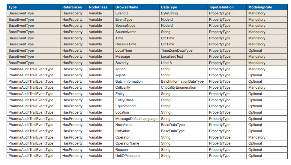
Table 6.2: PharmaAlarmType – Including Inherited Attributes
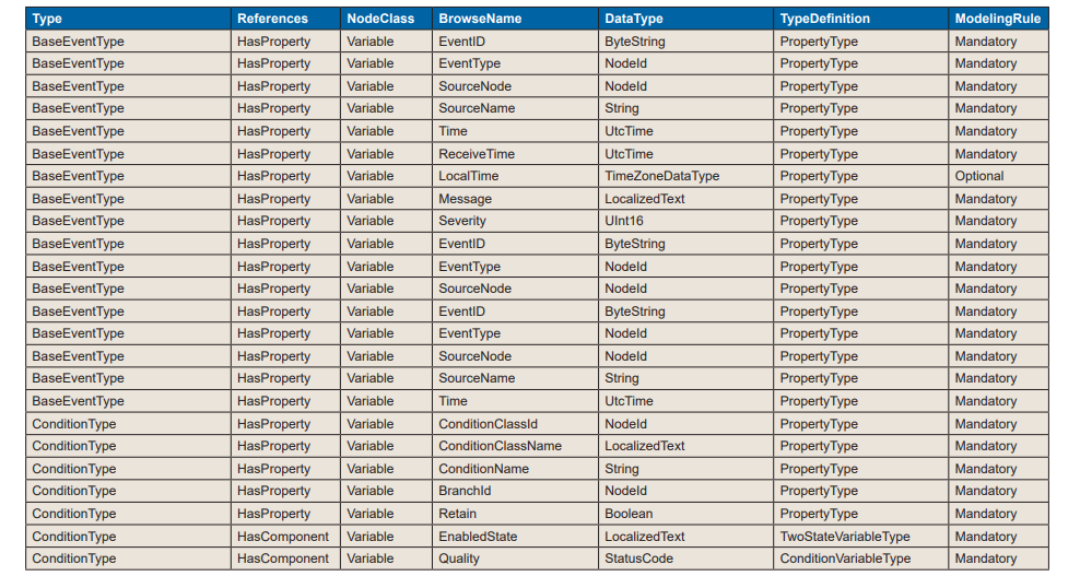
Table 6.2: PharmaAlarmType – Including Inherited Attributes (continued)
.png)
7 Acronyms and Abbreviations
| AML | Automation Markup Language |
| CPP | Critical Process Parameters |
| CSV | Comma Separated Values |
| EBR | Electronic Batch Record |
| EHS | Environmental Health and Safety |
| ERP | Enterprise Resource Planning |
| GMP | Good Manufacturing Practice |
| GxP | Good “x” Practice |
| HMI | Human-Machine Interface |
| IPC | In-Process Control |
| IT | Information Technology |
| KPI | Key Performance Indicators |
| MES | Manufacturing Execution System |
| MTP | Modular Type Package |
| OPC | Open Platform Communications |
| OT | Operational Technology |
| PEA | Process Equipment Assembly |
| PLC | Programmable Logic Controller |
| POL | Process Orchestration Layer |
| SCADA | Supervisory Control and Data Acquisition |
Limitation of Liability
In no event shall ISPE or any of its affiliates, or the officers, directors, employees, members, or agents of each of them, or the authors, be liable for any damages of any kind, including without limitation any special, incidental, indirect, or consequential damages, whether or not advised of the possibility of such damages, and on any theory of liability whatsoever, arising out of or in connection with the use of this information.
© 2024 ISPE. All rights reserved.
All rights reserved. No part of this document may be reproduced or copied in any form or by any means – graphic, electronic, or mechanical, including photocopying, taping, or information storage and retrieval systems – without written permission of ISPE.
All trademarks used are acknowledged.
Acknowledgements
By the ISPE Pharma 4.0™ Plug & Produce Working Group
This Concept Paper represents the outcome of work done by the members of Workstream 1 – End-to-End Connectivity – of the ISPE Pharma 4.0™ “Plug & Produce” Working Group as well as experiences and input from the individuals listed and does not reflect the views of any one individual or company.
Document Authors
Matthias Arnold AixEngineers Germany
Jouni Aro Prosys OPC Ltd Finland
Florian Bruck Rockwell Automation GmbH Germany
Rod Hoffman AstraZeneca USA
Stefan Krauss Siemens Germany
Heiko Lamers Inmation/Aspentech Germany
Giuseppe Menin COPA-DATA Italy
Klaus Sauermann Koerber Software (Werum IT Solutions GmbH) Germany
Rolf Helge Traut Takeda Pharmaceuticals Switzerland