Unique Identification on Primary Containers to Drive Product Traceability & Quality

The purpose of this document is to obtain feedback from practitioners on the issues and challenges that may be faced if and when uniquely identified primary containers for parenteral products are implemented within their manufacturing operations.
Health authorities and regulators are increasingly looking for much higher levels of traceability during the manufacture of parenteral medicines. The most common processes and technologies applied to achieve compliance are now reaching their technical limitations and as such, new approaches are needed to deliver the traceability requirements.
Traceability at the individual container level could become very important to drive patient safety through the prevention of product mix-up. There are other strong business drivers for uniquely coded containers. These include improved batch visibility and accountability while simplifying investigation work in the case of potential deviations during fill and finish operations. This reduces risk and can limit the direct financial impact from missed revenue or drug shortages.
The purpose of this document is to obtain feedback from practitioners on the issues and challenges that may be faced if and when uniquely identified primary containers for parenteral products are implemented within their manufacturing operations. In addition, we are seeking feedback on the proposed technologies and solutions described in this document as well as any additional use cases.
This ISPE Discussion Paper outlines:
- The rationale behind the development of parenteral containers with a unique identity
- Feedback from a survey of industry related to considerations necessary to help build a business case
- The current state of implementation of unique container identification technology in parenteral manufacturing lines including potential solutions
- A summary of challenges/questions that the technology developers face to finalize and develop the robustness of the solution
A process has been developed that delivers individual identification of primary glass containers for parenteral drugs. This technology has been extensively tested at a Proof of Concept level and is now moving into the Industrialization Phase.
In parallel to the development of the technical solution, the value proposition and the business case have been created for a range of pharmaceutical products from vaccines to biologics. Furthermore, this approach has been validated by a cross section of pharmaceutical manufacturers, presenting a compelling business case.
The development of this Discussion Paper has involved representatives from a cross section of stakeholders within the pharmaceutical industry. The objectives were to provide a better understanding of the requirements for the use and implementation of uniquely identified containers in the pharmaceutical manufacturing of parenteral products. Secondly, to deliver a discussion document that can form the basis of an implementation standard for use by the industry.
We are seeking input from colleagues working in fill and finish operations and device assembly operations of parental drug products to understand:
- Have all your potential use cases been covered? If not, what has been missed?
- What are the perceived challenges of implementing this solution?
- If your opinion, how can these be overcome?
- What additional discussion or data is needed for this to become the basis of a standard for the industry?
A feedback form may be downloaded HERE if you would like to answer these and other questions. Please direct all feedback to papersfeedback@ispe.org. The paper may be modified or expanded to reflect additional input.
1 Introduction
Health authorities and regulators are increasingly looking for much higher levels of traceability during the manufacture of parenteral medicines. The most common processes and technologies applied to achieve compliance are now reaching their technical limitations, driving the need for new approaches to deliver the traceability requirements.
Today, there is no individual identification of primary glass containers. Many solutions have been introduced, but none have been implemented as a large-scale manufacturing standard. This lack of traceability means that in the case of a problem in a process step, manufacturers are not able to define exactly which products have been impacted, and so adopt either an “over segregation” or “full batch write off” policy. These policies not only have a direct financial impact from lost or missed revenue, but also impact the fight against drug shortages.
A uniquely coded container would improve the quality and process control at drug product manufacturers by providing insight into each process to facilitate analysis and corrective action. Container serialization could be used to improve batch accountability, minimize drug product mix-ups, and reduce deviation occurrences.
2 Industry Feedback
The Parenteral Drug Association (PDA) research group recently conducted a survey 1 within its membership to understand the industry view of unique container identification. This survey was intended to learn more about how companies that manufacture parenteral drug products are working to improve tracking efforts and to see if serialization is the future for primary packaging components.
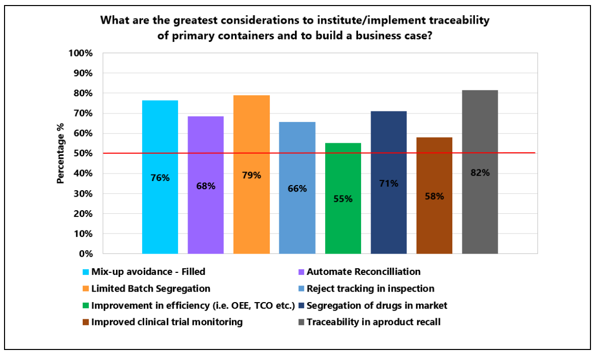
The “2019 PDA Traceability of Primary Packaging Survey” 1 was published in January 2020 by the PDA Prefilled Syringe Interest Group (PFS IG). The data in Figure 2.1 illustrates the overall view of the participants of the survey, which came from a cross section of the industry.
The organizations that participated in the survey develop, manufacture, or contract manufacture liquid and lyophilized parenteral drug products. The participants represent a broad span of the industry with a good distribution of small and large companies, multiple product types, and global presence. The four graphs in Figure 2.1 summarize the information received through the PDA survey.
Figure 2.1: Summary of the 2019 PDA Traceability of Primary Packaging Survey
© PDA, Inc. Reproduced with permission.
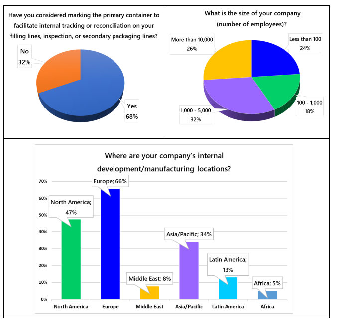
The results indicate an interest in primary container serialization and corroborate the initial value propositions presented in this ISPE Discussion Paper.
3 Solution Outline
This Discussion Papers proposes a solution to the issues of individually identifying primary glass containers. This solution is based on providing each glass container used for parenteral medicines with a Unique Identifier/code (UID). The generation of the UID uses the concept of serialization, which has been implemented for secondary packs for regulatory compliance. The UID is marked on the container as a machine readable GS1 ECC 200 – 2D data matrix barcode 2 to enable reading of the code during the different production processes.
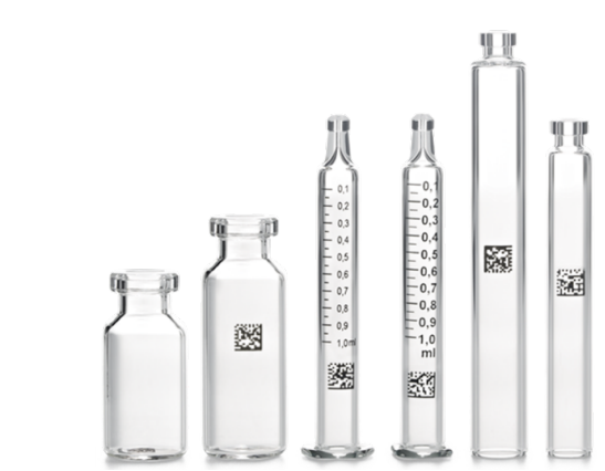
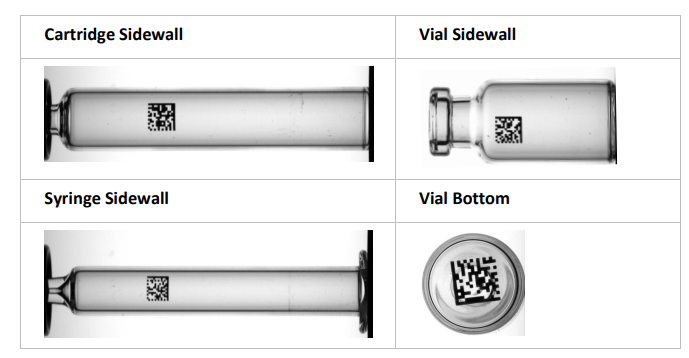
The UID will provide unit-level tracking from the glass-forming stage through filling and inspection to any applicable device manufacturing organization, and ultimately to the end customer. It will allow manufacturers to understand better the lifecycle of their drug product in the Container Closure System (CCS) and trace issues back to manufacturing and packaging processes, fostering continual improvement opportunities. Figure 3.1 illustrates potential barcode locations for the UID.
Figure 3.1: Containers with a Unique Identifier
Photo courtesy of Stevanato Group.
3.1 Rationale
The current challenges for the industry are related to increasing product complexity, lower volumes, and higher flexibility requirements, along with increased requirements for product traceability, both internally and from regulators.
Today, all glass containers are identical during manufacturing operations, be it component forming, product filling, visual inspection, or device assembly, making it challenging to proactively identify problematic locations within their processes when an issue is observed. The implementation of a UID strategy for primary packaging containers would change this by allowing for single container visibility throughout the manufacturing process and ultimately to the patient. This data could be used to link observed defective units to a specific process or process location, thus enabling focused root cause analyses and continual improvement activities.
Parenteral product manufacturers utilize comprehensive visual inspection processes to monitor the quality of their production. They utilize data from their process to establish normal rejection rates and evaluate those rejections for trends to drive improvements within manufacturing operations.
These concepts have been reinforced with the publication of an updated version of the USP <1790> Visual Inspection of Injections 3. This document established an enhanced responsibility of manufacturers to analyze their inspection rejection rates to identify trends, drive continuous product quality improvement, and if an issue is identified, to determine root causes.
The inspection data monitoring must be done on a periodic basis and utilize sound Statistical Process Control (SPC) principles. Action levels need to be set based on this analysis to determine if these levels reflect the correct process capability along with validated alert levels for each process 3. This monitoring can be hindered with unmarked containers as it is challenging to correlate observed defects back to a specific part of the manufacturing process.
With container traceability one could determine from which container a deviation started and correlate the deviation back to the process. Additionally, UIDs allow manufacturers to better control their manufactured inventory during processing (e.g., visibility of batch unit counts, potential decrease in drug product mix-ups, etc.) Thus, the adoption of a UID strategy provides the industry with a powerful inventory control and investigational tool that allows for more targeted continual improvement opportunities compared to the current environment.
3.2 Process Status
Development of applying a UID to primary glass containers for parenteral drugs was undertaken to satisfy this need for increased process and product traceability. The technology has been extensively tested at a Proof of Concept (PoC) phase and is now moving into the Industrialization Phase.
4 Current State of Implementation
4.1 Unique Identifier (UID) Configuration
4.1.1 Existing Regulatory Mandates
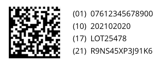
There are currently several international regulations4,5, 6 covering serialization and, in some cases, traceability of the secondary pack of prescription medicines. The mandates generally use the GS1 standards that require the inclusion of four pieces of data into the 2D data matrix barcode: Global Trade Item Number (GTIN), Unique Identifier (UID), Batch Number, and Expiry Date, as illustrated in Figure 4.1. The full string of characters encoded into the barcode defines a barcode size of 10 mm x 10 mm to 12 mm x 12 mm. These barcodes are marked onto cardboard cartons, which are flat and absorbent, using standard serialization printers.
Figure 4.1: Sample Product Identifier with 2D Barcode
4.1.2 Parenteral Container Challenges
Unfortunately, in the case of glass containers for parenteral medicines, the operating conditions are more complicated:
- The surface is curved with diameters as small as ø= 6.85 mm
- Marking is on a glossy, non-absorbent Type 1 glass surface
- Requires positional flexibility for the marking of the barcode
- High speed barcode readability is needed at a variety of processes speeds and operational checkpoints
If these conditions are not addressed, increased factory/product loss due to an inability to read a 2D matrix may result.
The Table 4.1 indicates the Min-Max dimensions of key standard parenteral containers.
| Product | Description | Diameter Ø | Length L |
|---|---|---|---|
| Vials | 2ml Vial | 11.90 mm | 32.0 mm |
| 100 ml Vial | 51.6 mm | 110 mm | |
| Syringes | 0.5 ml | 6.85 mm | 57.5 mm |
| 1.0 ml | 8.15 mm | 64.0 mm | |
| 2.25 ml | 10.85 mm | 65.4 mm | |
| Cartridges | Min | 8.15 mm | 64.0 mm |
| Max | 10.85 mm | 65.0 mm |
As a result, the normal serialization standards required by the European Falsified Medicine Directive (EUFMD) 4, the USA Drug Supply Chain Security Act (DSCSA) 5, or Russian Federal Law No. 425-FZ 6 mandated for secondary packaging do not translate directly to the glass container sizes detailed in Table 4.1. To enable the unique identification of containers, these standards must be the baseline for this solution. However, the approach must be adapted to manage the unique conditions and use cases seen in parenteral medicine operations.
4.1.3 Unique Identifier
Currently the global market for parenteral containers using tubular glass is around 18 billion containers per annum 7. The breakdown by type for 2019 and the estimated volume for 2023 is shown in Table 4.2.
| Product | Volume 2019 (Billion) | Volume 2023 (Billion) |
|---|---|---|
| Prefilled Syringe | 3.5 | 4.5 |
| Vials | 10 | 11 |
| Cartridges | 3.8 | 4.0 |
| Totals | 17.3 | 19.5 |
In a serialization strategy, the UID should be unique for a minimum of the individual drug product shelf life plus two years – 5 years for most drugs. Applying a uniqueness factor of 5 to the calculation means that the UID should be chosen from a pool of at least 100 billion codes. To be certain we can apply a factor of 10, and this would equate to 200 Billion codes.
Taking this into account, along with the product and marking requirements, the UID should be 8 alphanumeric characters. This will deliver 2821 billion codes, which will ensure that the chance of an overlap or two codes being the same will happen once in every 144 years.
Statistically, it is possible that two codes of the same identity could be generated by different systems and suppliers. The chance of this is a 1 in 2821 billion, so it is statistically insignificant. More importantly, the chance of the same code being on the same type of container for a single pharmaceutical manufacturer using the same Drug Substance (DS) batch on the same filling machine is again statistically insignificant. Combining these two factors means that the chances are infinitesimally small and essentially zero. However, the data that is attached to the code during its lifecycle will make it unique from the day is marked.
Table 4.3 illustrates the rationale for choosing an alphanumeric code over numeric codes for the serialization strategy.
| Number of Characters | Alphanumeric Combinations | Numeric Combinations |
|---|---|---|
| 1 | 36 | 10 |
| 2 | 1,296 | 100 |
| 3 | 46,656 | 1000 |
| 4 | 1,679,616 | 10000 |
| 5 | 60,466,176 | 100000 |
| 6 | 2.18E+09 | 1000000 |
| 7 | 7.84E+10 | 1.00E+07 |
| 8 | 2.82111E+12 | 1.00E+08 |
| 9 | 1.0156E+14 | 1.00E+09 |
| 10 | 3.65616E+15 | 1.00E+10 |
| 11 | 1.31622E+17 | 1E+11 |
| 12 | 4.73838E+18 | 1E+12 |
4.1.4 Structure
Most pharmaceutical manufacturers have multi-vendor sourcing strategies. In order to manage traceability of the containers to different vendors, a prefix has been requested to provide vendor visibility. The advantage of a prefix is that it will increase the uniqueness factor, but the additional character will increase the size of the barcode. With small-sized containers such as the 0.5 ml and 1.0 ml syringe, the barcode will cover a greater area of the curved surface of the glass container, which can affect the readability of the 2D barcode. Codes with 8 alphanumeric characters have been proven to have good readability on a small syringe 7.
4.1.5 UID Management
Approximately 80% of the world’s prescription medicines are covered by serialization mandates, as detailed above. To achieve compliance, pharmaceutical companies have made significant investments in serialization systems at a line (L3) and at a corporate level (L4) 8.
The L4 system will generate, manage, and store the UID/serial numbers along with other functionalities. Any system used for primary container serialization should follow the same protocols and requirements used for the serialization mandates. This will leverage the existing standards, suppliers, and databases, and the ability to share data between different systems.
At the PoC phase, an L4 data management system has been developed that is in line with the existing mandates but with some changes to manage the processes and use-case requirements of the parenteral containers.
4.2 UID Marking
4.2.1 Marking Process
There are several key characteristics that are required from a marking process.
- It must be a digital process that can manage high speed serial number and barcode generation and marking
- It must have no impact on the container integrity and the mechanical properties of the glass
- It must not be impacted by or impact any of the pharmaceutical sterilization process methodologies (e.g., steam sterilization, irradiation, Ethylene Oxide (EtO), etc.)
- It must have minimal impact on the manufacturing lines of the glass converter and pharmaceutical company including filling, inspection, and device assembly as appropriate
- It must be readable with standard off-the-shelf serialization camera systems
Based on these characteristics, a digital printing process that uses ink systems capable of withstanding both the process temperatures and residence time greater those found in depyrogenation sterilization methods is preferred. Inorganic ink systems are required because standard organic inks are destroyed by typical sterilization process temperatures. Laser systems could be considered for marking; however, the potential impact to the container integrity must be taken into account as laser marking alters the glass surface.
There are several standards that support a serialization strategy:
- GS1 ECC 200 – 2D Data Matrix2
- GS1 Electronic Product Code Information Services (EPCIS) 9
- ISO 15415 – 2D barcode symbol print quality specifications1 10
- ISO 29158 – Automatic identification and data capture techniques Direct Part Mark (DPM)2 11
- European Falsified Medicine Directive 4
- DSCSA 5
- FDA 21 CFR Part 11 Compliance 12
- ISPE GAMP® Guidance Series 13
Note 1: The grading standard ISO 15415 10 was created for a laser or inkjet printing process on a cardboard carton, which is flat, easily marked, and absorbent. This standard does not apply to a product that is reflective, circular, uses a specific marking process, and does not absorb ink (e.g., glass containers).
In its pure form this standard cannot be applied to the barcode. However, it is a very good guide to the quality and readability of the barcode. Furthermore, there are several standard cameras from different manufacturers with the capability to verify the grade of the barcode in real time. This ISO standard should be used as a reference for the readability of the barcode.
Note 2: Marked glass containers have similar characteristics to DPM and it is recommended that this standard is used as an additional reference11.
4.2.2 Barcode Type and Sizing
The size and curvature issues related to the container, discussed in Section 4.1.2, lead to the conclusion that the UID needs to be encoded in a GS1 ECC 200 – 2D Data Matrix barcode. This has two forms: square and rectangular. Both barcode forms contain the same data, but the rectangular format is more suited to the smaller diameter container sizes where the available print surface is limited.
Barcode sizing is related to data content and the “dot size” of the marking technology. The printing technology described requires a dot size of 0.4 mm. As such, Tables 4.4 and 4.5 dictate the possible barcode sizing.
| Numeric Digits | Alphanumeric Characters | Recommended Minimum | Recommended Maximum | ||
|---|---|---|---|---|---|
| Module size (mm) | Printed Size (mm × mm) | Module size (mm) | Printed Size (mm × mm) | ||
| 6 | 3 | 0.3 | 3.0 | 0.4 | 4.0 |
| 10 | 6 | 0.3 | 3.6 | 0.4 | 4.8 |
| 16 | 10 | 0.3 | 4.2 | 0.4 | 5.6 |
| 24 | 16 | 0.3 | 4.8 | 0.4 | 6.4 |
| 36 | 25 | 0.3 | 5.4 | 0.4 | 7.2 |
| 44 | 31 | 0.3 | 6.0 | 0.4 | 8.0 |
| Numeric Digits | Alphanumeric Characters | Recommended Minimum | Recommended Maximum | ||
|---|---|---|---|---|---|
| Module size (mm) | Printed Size (mm × mm) | Module size (mm) | Printed Size (mm × mm) | ||
| 10 | 6 | 0.3 | 2.4 × 5.4 | 0.4 | 3.2 × 7.2 |
| 20 | 13 | 0.3 | 2.4 × 9.6 | 0.4 | 3.2 × 12.8 |
| 32 | 22 | 0.3 | 3.6 × 7.8 | 0.4 | 4.8 × 10.4 |
| 44 | 34 | 0.3 | 3.6 × 10.8 | 0.4 | 4.8 × 10.5 |
| 64 | 46 | 0.3 | 4.8 × 10.8 | 0.4 | 3.2 × 7.2 |
| 98 | 72 | 0.3 | 4.8 × 14.4 | 0.4 | 3.2 × 12.8 |
4.2.3 Barcode Positioning
The position of the barcode on the container is dependent on the use cases and manufacturing processes used by each pharmaceutical company. Table 4.6 lists the most appropriate position for the marking of the 2D barcode.
Photos courtesy of Stevanato Group.
| Product | Recommended | Not Recommended | Diagram |
| Syringes |
|
| 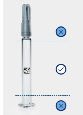 |
| Cartridges |
|
| 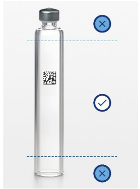 |
| Vials |
|
| 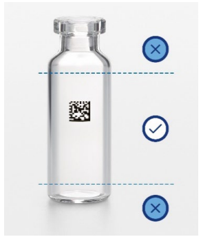 |
| Vials – Base |
|
| 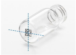 |
4.2.4 Readability
The key driver for any barcode is readability, and this is particularly important when the products are curved, reflective, and are being read at high speeds in machines.
As detailed in Section 4.2.1, there are two standards in common use for reading codes with square modules (for example, AIM DPM for dot matrices). They are:
Today many standard camera systems have embedded software to verify the grade of the barcode. They use the same system of measurement as the grading system, but the lighting and other operational conditions are different to those defined in the standard.
In addition, in its pure form ISO 15415:2011 10 cannot be applied to the barcode as it was designed to grade barcode printed on flat cardboard surfaces, which have been marked with standard marking systems. However, it is a very good guide to set the quality and readability specifications of the barcode, and it should be used as the reference standard for the readability of the barcode.
During the grading process, grading systems look at and evaluate 16 parameters of the barcode to arrive at the final grading. The grade of a code is designated with a letter from A, B, C, D, or F, with A being the best and F the worst.
The result of a grade test is defined by embedded software algorithms after looking at each of the parameters. Figure 4.2 shows the way in which a barcode is graded using ISO 15415 10, but the same process is also used for the ISO 29158 standard 11.
Figure 4.2: ISO 15415 Barcode Grading Parameters 10
Used with permission from Cognex International, www.cognex.com.
©ISO. This material is reproduced from ISO/IEC 15415:2011, with permission of the American National Standards Institute (ANSI) on behalf of the International Organization for Standardization. All rights reserved.
![Figure 4.2: ISO 15415 Barcode Grading Parameters [10]](/sites/default/files/concept-papers/Unique%20Identification/figure%204.2.PNG)
A 2D barcode symbol can only be graded if it is read under the specific conditions described in the standard. In the real operating conditions of a production line, the lighting, speed, and camera systems will be different from a defined grading camera. To ensure full compliance with the standard, the grade obtained by the production equipment must be compared with the grade obtained in the controlled environment of a grading camera. It is desirable to harmonize the reading setup between the in-line camera systems and the grading camera.
4.2.5 Testing
The following tests are typically considered when evaluating the suitability of any marking process used on primary containers for parenteral products. Many of these tests are regarded as “used for both product introduction and batch release of the containers.” This is not the full list as different pharmaceutical manufacturers have different test needs based in their processes and products.
- Ink migration tests
- Scratch test
- Accelerated ageing tests
- Stress analysis
- Leachable and extractable tests
- Acid attack test
- Ph. Eur. 2.6.1 Sterility tests 14 or equivalent
- Dimensional tolerance consideration for device use
- Barcode readability testing
4.3 Filling Processes
Aseptic filling is a complex business with the potential for contamination throughout the process. In the event of a problem in a process step, manufacturers are not able to define exactly which products may have been impacted and so adopt either an “over segregation” or “full batch write off” policies. The use of uniquely identified containers increases process traceability, with the potential to reduce the amount of unaffected (“good”) product discarded.
Filling machines collect large amounts of information during the process that can provide detailed visibility of the process. The challenge is that without a unique identifier on each container the data cannot be associated with a specific container. If a UID is used, the data can be associated with the exact container, thus providing the full history of the container in the machine and detailed traceability data.
The container formats commonly used in aseptic filling are purchased from a supplier as sterilized or unsterilized. Ready-to-Use (RTU) containers arrive sterilized and ready to be filled. The container supplier has performed all the required process steps and the products are delivered sterilized in a sealed tub. The second format is the bulk process in which the pharmaceutical manufacturer performs all the required steps to deliver a sterile container to the filling line. The use of RTU and bulk formats varies by customer and container.
4.3.1 Ready-to-Use (RTU) Formats
The RTU format is comprised of a nest that holds the containers. These containers have been washed, siliconized (if applicable), inspected, and sterilized. The nest is placed into a plastic tub, covered with a Tyvek® sheet/liner and heat sealed with a Tyvek® lid. Each tub then placed in a single or double sterile bag followed by sterilization using EtO.
The tub is delivered individually to the filling line, where upon entry, the tub may be sterilized using e-beam or Vapor Hydrogen Peroxide (VHP) to remove outside contamination. The outer sterile bag is removed while entering the sterile area, and the second bag is removed while entering the filling area. The glued Tyvek® lid and loose Tyvek® sheet are removed when the tub is in the sterile area immediately prior to filling (or de-nesting). Once the filling process is complete each container is stoppered to complete the aseptic process.
4.3.1.1 Syringes
Almost all glass syringes (typically assumed to be 90%) are used in the RTU format.
Most filling machines use the nest as the product management and transport mechanism during the filling process. When the tub enters the aseptic area, the nest is lifted out of the tub and inserted into a nest fixing frame to provide a fixed position for every object. In this situation, readability of each syringe is a challenge as the syringe needs to be removed or lifted from the nest for the barcode to be read. Lifting the syringe out of the nest in the installed machine park may be difficult, not only because of space constraints, but also because of the possible impact on the validation of the process. A concept called product aggregation can be used to overcome this challenge and is discussed in more detail in Section 4.4.
4.3.1.2 Vials
Increasingly, RTU formats are used for the supply of vials. Unlike syringes, most of the machines remove the vials from the nest. This facilitates the reading of the code, but more detail needs to be provided about the position of the code and the types and position of cameras to enable single unit visibility and traceability.
It is also possible for the vials in the RTU format to use an aggregation process to deliver the UID and the position of each vial in the nest, discussed in Section 5.3. The process described above would be used in the same manner but would be adjusted for the size, quantity, and type of vial in the nest.
4.3.2 Bulk Products
The second option is where unsterilized glass containers are delivered to the pharmaceutical company in bulk packaging formats.
4.3.2.1 Syringes
The bulk handling of syringes is usually associated with quality requirements such as 100% weighing, camera inspection, etc. To be processed, it is necessary to de-nest the syringes. Usually, nests get lifted out of the tub and the syringes are de-nested and passed through a washing, siliconization, and depyrogenation sterilization process before filling. Once the filling process is complete the syringes are placed back into the nest and into the tub.
Reading the syringe is much easier in this environment as they are moving as single units and the reading station can be implemented in the machine. However, product aggregation would also help in this environment, as described in Section 4.4.
4.3.2.2 Vials
Currently most vials are supplied in bulk packaging. They are delivered in a range of packaging forms from sealed dust-free trays to shrink-wrapped packages as defined by the specifications of the pharmaceutical manufacturer.
Vials are delivered to the line, unwrapped, and removed from the tray, then go through different process steps depending of the specific requirements of the line. Prior to filling, standard process steps are washing, siliconization (optional), and heat depyrogenation.
During the filling operations, the vials move as single units to the filling needle. Placing the barcode on the base of the vial simplifies reading the code. The position and size of the barcode has been detailed in Tables 4.4, 4.5, and 4.6. However, production lines can vary and thus the specific use cases for each line need to be studied to provide more detail about the position of the code and the types and position of cameras to enable single unit visibility and traceability.
Once filled the vials may undergo additional steps such as safety gassing and In-Process Control (IPC) testing before being stoppered and capped.
4.3.3 Filling Machine Product Data
The application of a UID to a container is designed to improve the product and process traceability within the internal manufacturing operations from filling through inspection to device assembly, etc. Modern machines store large quantities of data in a database held within the machine. This covers product data as well as conditions in the filling process.
The information in Table 4.7 is representative of the level of detail that can be obtained with a UID strategy, although the type of data may vary by machine manufacturers.
Table 4.7: Example Information Available for Each Unit using the UID Strategy
Used with permission from OPTIMA pharma GmbH, https://www.optima-packaging.com/en/pharma
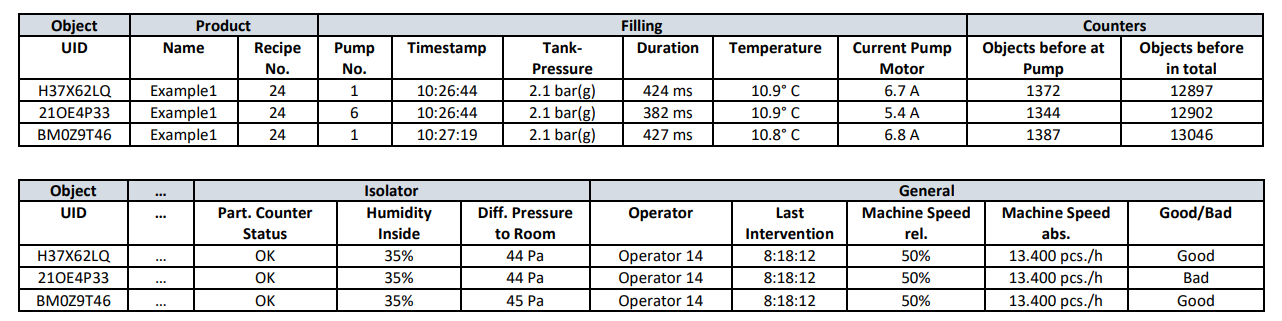
The association of these parameters with the UID provides manufacturers with unit-level visibility of the manufacturing conditions and process parameters. These data points can be provided as a report, although the content may vary by machine manufacturer.
4.4 Nest/Container Aggregation
The aggregation process has been developed by the authors to simplify the introduction of the use of the unique containers by eliminating the need to read each of them in the RTU filing lines. This will simplify implementation and reduce the possible impact on the validation of the process.
This system works by creating an electronic parent and child relationship between the container and the nest. The technique is widely used in the industry for secondary packs for regulatory compliance with the US DSCSA 5 where a relationship is created between the secondary packs and shipping packaging. In the case of primary containers, the focus is on building the relationship between the containers and the nest/tub.
There are two benefits of the aggregation process. Firstly, the aggregation process allows each UID to be associated with a specific nest, which itself has a unique identity and 2D barcode. All the data is tied to the unique identity of the nest to ensure traceability within the RTU process. Secondly and more importantly, only one data carrier needs to be written and read to supply all the key data to the filling machine thus simplifying the UID implementation in the filling process
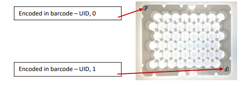
Machines handle the nest in different ways when it enters and is used in the filling line. In order to overcome this challenge, the UID position in the nest is defined relative to specific position markers on the nest during the RTU process. Each nest is marked twice with a 2D data matrix barcode at opposite corners. The barcodes contain the same unique serial number/UID.
In addition, they contain the information indicating which of the two barcodes of the nest each one is. For example, the UID barcode on the top left corner of the nest is appended by 0 and the bottom right barcode is appended by a 1. The numbers are also printed on the nest alongside the barcode so that there is a human-readable marker of the orientation. The UID is then used in the aggregation process to create a parent and child relationship between all UIDs contained in the nest (children) to the nest UID (parent).
The nest configuration varies depending on the product type and size, but the concept and method are shown in Figure 4.3.
Figure 4.3: Barcode Placements on Nest
Once the nest enters the filling machine, a simple 2D Data Matrix Code (DMC) camera can be used to locate and read the barcodes to define the orientation of the nest and the locations of each UID relative to the nest orientation.
A Read/Write (RW) tag on the tub with Radio Frequency Identification (RFID) delivers an effective method to not only store the product characteristics but more importantly, the UID information in relation to the container’s position inside nest. This approach simplifies the process in the filling line and removes the need to read each container. This data can be passed directly to the shift register to deliver machine and process traceability. For data security and the standardization of the reading protocols, an ISO 15693 standard 15 High Frequency (HF) chip is used.
The tub can have its own UID different to the one that is printed on the nest or it can use the existing unique identifier that each RFID chip has as standard. Using the existing identifier facilitates the use of the same chip throughout the manufacturing steps without creating an issue with nesting, de-nesting, and partial tubs in the process.
To prevent any possible mix-up of nest and tubs in the RTU process, an electronic relationship is created between the two components. The UID of the nest is connected electronically in the aggregation software with the chip UID. This can be checked and validated by checking both the physical and the electronic relationships for the nests and tubs before they leave the RTU lines.
A RW RFID tag is centered on the base of the tub. Figure 4.4 illustrates the positioning of the chip.
Figure 4.4: Position of an RFID tag on the Base of a Tub
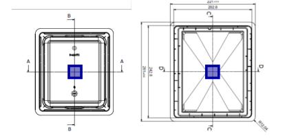
This allows the reader to be in the base of the infeed as there is space in the machine and it does not have an impact on the laminar flow in the machine. The reader delivers the supplier data and the product format, as well as the UIDs in relation to each container’s position in the nest. It also helps define the nest orientation so that each object can be identified uniquely for all filling machine manufacture formats.
During the filing processing, the order of the objects can get mixed up for reasons such as IPC testing or removal of bad objects. The RW RFID product aggregation systems will aid in the continuous tracking of the objects once they have been re-nested and leave the process. If a change occurs to the relationship between the UID, nest, and tub, then the aggregation relationship should also be rewritten.
Using a RW RFID chip allows it to be a process-data carrier providing a method to track the movement of each UID container through the inspection processes, device assembly (if applicable), and packing operations if needed.
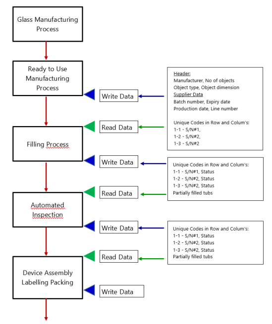
The data handling and processing steps within the filling machines include:
- Removing the packaging
- Reading the serial number of the nest together with the nest orientation
- Checking the match of RFID tub serial number with the nest DMC serial number
- Reading the RFID tag with UIDs and positions and transferring this data to the electronic shift registers
- Transferring the product and supplier data to the shift register
- Lifting the nest from the tub
- Filling and inspecting the container while keeping track of all UIDs
- Deleting the UID positions and tub serial number in the RFID tag to represent an empty tub
- Re-nesting the syringes
- Placing the nest back into the tub
- Retrieving electronic data from the machine databases
- Writing the new nest positions, tub serial number, DS code and batch number
- Releasing the nest and tub to the automated inspection process
The use of the chip facilitates a simple and effective method to transfer product, machine, and process data directly to the shift register to deliver machine and process traceability. The memory of each chip can be cleared and then written with the new UID location in the nest before it is passed to the next operation. An outline of the process flow is shown in Figure 4.5.
Figure 4.5: Ready-to-Use Nest and Tub – RFID Chip Flow Chart and Data Approach
4.5 Freeze-Drying Processes
4.5.1 Process Traceability
The production of many pharmaceutical drugs and heat-sensitive medications is inconceivable without the use of the Lyophilization (Lyo)/freeze-drying process. It is a process that requires close management to minimize process and product issues.
Traceability within the process can be a challenge when standard vials are used, particularly with older machines that may have various loading/unloading mechanisms. As discussed, in the event of a problem manufacturers are not able to define exactly which products have been impacted.
4.5.2 Lyophilization Machine Requirements
Uniquely identified containers enable manufacturers to know where the individual vials are positioned. Knowing the exact shelf/position of the vial within the freeze-drying chamber delivers a more accurate monitoring of the process, both during the validation studies and routine manufacturing.
Lyo machines have mobile plates to allow loading and unloading at a constant height. After loading the first upper shelf, it must be raised automatically, freeing the second shelf for subsequent loading and so on until the last bottom shelf. The process should run vice versa for unloading: after having unloaded the first bottom shelf, the second is lowered and unloaded and so on until the last upper shelf has been completed. However, there are a range of machine types on the market that may have one of the following loading/unloading processes.
4.5.2.1 Loading of the Freeze Dryer
This list outlines some of the industrial configurations for transferring vials from the filling and stoppering machine to the shelves of the freeze dryer chamber. The freeze dryers have movable shelves that are loaded one by one starting from the upper shelf.
- Manual Loading using Trays or Frames: The vials coming out from the stoppering station are collected in trays/frames, which are then loaded manually on the shelves of the freeze dryer
- Semiautomatic Loading: The vials are collected on the plate of a mobile trolley protected by a Laminar Flow Hood (LFH); the trolley is brought to the front of the freeze dryer and the vials pushed onto the shelves
- Automatic Loading (Row by Row): The vials come out in-line from the stoppering station, arrive in front of the entrance door of the freeze dryer (pizza door) and are pushed (row by row) on the shelves of the freeze dryer
- Automatic Loading (Shelf by Shelf): The vials leaving the stoppering machine are loaded onto a shelf in quantities corresponding to a whole or half shelf of the freeze dryer
4.5.2.2 Unloading of the Freeze Dryer
Unloading the freeze dryer can be done in the following ways:
- Manual Unloading using Trays or Frames: The vials from the trays/frames are loaded onto the buffering table of the crimping machine
- Semiautomatic Unloading: The vials are collected on the plate of a mobile trolley protected by a LFH and then loaded onto the buffering table of the crimping machine
- Automatic Unloading (Row by Row): The vials come out lined up by the freeze dryer and fed directly to the crimping machine buffer
- Automatic Unloading (Shelf by Shelf): The vials leaving the freeze dryer are fed directly to the crimping machine buffer
At a minimum, barcode-reading cameras should be positioned before and after the loading and unloading process to deliver increased traceability within the most critical process control areas. As the vials are transported individually at some point of the loading process, the best position for the barcode may be on the base of the vial with the camera positioned below the feed belt or wheel to track the UIDs entering and leaving the Lyo process. Adding this data to the shift register provides date and time stamps and thus greater insight into the process in the event of an issue.
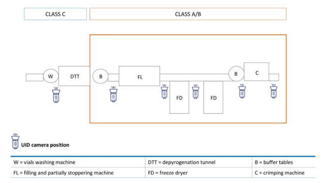
4.5.3 Line Layout
In a freeze-drying process, the vials are delivered as bulk containers that pass process steps to sterilize the container before it is filled and enters the freeze drying/Lyo chamber.
To deliver traceability for each process, cameras are required to read the UID codes. The position of the barcode and thus the cameras depends on each manufacturer’s process, but the best position for the barcode may be the base of vial as it can be read from the bottom by cameras positioned underneath the container transport conveyors.
Minimally, barcode readers and cameras need to be installed before and after the Lyo machine. However, adding cameras before and after each process delivers traceability for each step and data about each process. Adding the UID to the shift register of the machines/production line provides single container insight into each process as well as the overall production line.
The layout shown in Figure 4.6 has been suggested as a reference example.
Figure 4.6: Example Line Setup Showing Barcode Reader Camera Positions
4.6 Automated Inspection Systems
Automated inspection machines are a key part of parenteral drug manufacturing. As it is a key process, it is seeing increased regulatory scrutiny.
The updated version of USP <1790> Visual Inspection of Injections 3 places the responsibility on manufacturers to look at and analyze trends in inspection systems. It is not enough to inspect and reject, but manufacturers must determine the normal reject rate and, in case of a deviation (or a trend), investigate for the root causes based on sound SPC analysis 16. Using uniquely identified containers allows personnel to accurately determine from which container the deviation started and correlate the deviation with the process.
All filled containers (vials, cartridges, or syringes) are inspected using a range of camera systems to verify the product and the container quality. This includes the cosmetics, particulates, the CCI, cracks, etc. Due to the requirements for the inspection, the whole container circumference and the bottom offer free visible access at specific inspection station(s). Container rotation is also a standard feature in most inspection systems. These conditions simplify the reading of the 2D DMC.
Because most automated inspection systems can read the 2D DMC directly with the camera systems, there is no difference between the bulk and tub/nest processes.
For a tub/nest inspection, an additional RW RFID is required at the infeed and at the outfeed of the inspection process.
4.6.1 Cameras and 2D Barcode-Reading Algorithm
The architecture of the Data Matrix DMC200 Code is described in ISO/IEC 16022:2006 17. ISO standards are included and enhanced in the GS1 Data Matrix Guideline 2. The code is very robust, and includes a specific algorithm: the Reed-Solomon Error Correction Algorithm. This algorithm allows for correct reading of the DMC even if a portion of the bar code is damaged or missing. This helps with processing and readability of the DMC.
There are many software implementations on the market to decode the DMC and read its content. These are integrated into code readers, smart cameras, and PC-based vision systems. Any of these systems could be used in the inspection machine. Example images are provided in Figure 4.7.
Figure 4.7: Example Inspection-Machine Images
4.6.2 Inspection-Machine Performance
The key question with regards to placing a UID on primary containers for automated inspection systems is of course, whether the chosen UID will have an impact on the inspection results (inspection-machine performance) as critical defects might be covered by the 2D barcode marking.
Preliminary data has been collected for both a clear liquid and a suspension on a test run of 7800 units of the standard 3 ml cartridge. The data collected shows that the two different solutions have a DMC position where there is minimal impact (less than < 0.1%) on the performance of the inspection process 18. However, these tests need to be repeated on the different formats in significantly higher volumes – standard batch configurations - to ensure that the inspection machine performance is not impacted.
4.7 Data Management
Unique containers facilitate traceability in the various production processes through to the end consumer. Pharmaceutical manufacturers have made significant investments in serialization to achieve regulatory compliance, drive continuous improvement initiatives, and improve quality and control. A key objective should be to ensure simplified integration of any data created and associated with the UID strategy. All the data MUST be stored and managed to facilitate EPCIS (GS1)4, 5. EPCIS is a global GS1 Standard for creating and sharing visibility event data, both within and across enterprises, and applies to all situations in which visibility event data is to be captured and shared 9.compliance, drive continuous improvement initiatives, and improve quality and control. A key objective should be to ensure simplified integration of any data created and associated with the UID strategy. All the data MUST be stored and managed to facilitate EPCIS (GS1) 4, 5. EPCIS is a global GS1 Standard for creating and sharing visibility event data, both within and across enterprises, and applies to all situations in which visibility event data is to be captured and shared 9.
4.7.1 Traceability Data
The content of the 2D code is a unique identifier of the individual container and is used for tracking the container throughout the manufacturing process. While the container is out of the tub, the barcode can be used to track its identity. When inside of the tub, the container is tracked using the RFID chip via the link between the position inside the tub and the individual container, so the container can be tracked throughout the process.
4.7.2 Meta Data
Having knowledge about the individual container gives the opportunity to extend the traceability with additional meta data linked to the individual identity.
Data could come from the container manufacturer and provide additional information about the container type, size, weight, etc. This data could be used to optimize the filling process with higher precision by taking small variations into account between the individual containers during drug product manufacturing activities.
The meta data could also be exported from the filling line, the inspection line, and other automated manufacturing lines as appropriate. Each part of the manufacturing process stores this data in its own data management systems in databases or similar storage solutions. By having a unique identity on each container, the data can be linked to the container and queried later in the process. An example of this is a detailed report of the grade of the barcodes linked to the individual codes.
4.7.3 Communication Interfaces
There will be data exchanged between the individual subsystems. Three interfaces have been identified:
- Individual Barcode: This code is read using a camera or a barcode reader
- RFID chip: This chip is read from and written to during the process using an RFID Writer
- Meta Data: This data is exchanged using the EPCIS standard in either a file or a web Application Programming Interface (API)
4.8 Labeling
During labeling, the label typically identifies the content of the syringe, cartridge, or vial. The label is human readable, the UID is not; the UID is intended for drug product/device manufacturing and distribution use and not to communicate key information to the end user.
The UID of the syringe, cartridge, or vial can be used to query the history of the container to ensure that the drug product contained in the syringe, cartridge, or vial is consistent with the data on the label.
Labeling is often done in bulk and is one of the process steps with possible readability of the UID.
Applying the label to the container directly is a common practice within the industry. Additionally, the label may be applied to a medical device containing the container, and not directly onto the syringe, cartridge, or vial. The syringe, cartridge, or vial UID may be obscured by the label, device, or packaging, but remains durable and discoverable.
The labeling operation can terminate or change the relationship of the syringe to the nest.
4.9 Optional Processes
The marking process for the unique containers has been developed to ensure that the 2D barcode is part of the container for the full shelf life. As a result, pharmaceutical manufacturers can use the barcode for additional/optional processes that can be implemented after automated inspection processes. This may include linking the primary container to the secondary pack and digital leaflets, or to simplify recalls or market investigation work.
These options can be implemented and handled internally by the pharmaceutical manufacturers but care should be taken to ensure that all the data collected in the manufacturing processes are matched and connected with the container without the possibility of product mix-up.
In case larger tests demonstrate that the inspection machine performance is impacted by the UID, the benefits will still be achieved even if the marking is applied right after the inspection.
5 Summary of Challenges that Technology Developers Face
A significant factor in the adoption of the UID solution is the ability to process it within existing installed machines with minimum impact on the existing operating procedures and validation. In order to achieve this, technology developers have tried to consider the range of possible use cases across all the key processes. However, not every use case has been considered, and so the feedback from the readers will add inputs and help to develop the robustness of the solution.
Furthermore, some of the concepts outlined in this Discussion Paper require additional time and testing resources to ensure that data is collected to support the process. Some of these have been identified in Table 5.1 but as indicated, there may be more.
| ITEM | QUESTION |
|---|---|
| 1. | In certain processes, reading the 2D DMC may be a challenge. Some cameras overcome this by using a “stitching process” to connect two partial codes to enable the readability of the barcode. This is dependent on the quality of the code as well as the position of the images. This needs further development and data collection to enable it to be added to the document. |
| 2. | A more detailed analysis on the readability of syringes outside of the nest and tub should be undertaken for the next version of the document. |
| 3. | What format will the RFID data take and how will it be compiled? |
| 4. | Do we need to consider the recyclability of the tubs with the RFID on them? |
| 5. | How do we ensure the integrity of the nest/tub relationship in the RTU process? |
| 6. | How do we validate that the right nest is in the right tub? |
| 7. | Can we define how we can retrofit existing machines in production to handle uniquely identified containers? |
| 8. | Is the integrity of the data stored on the RFID chip retained when it is exposed to either an EtO sterilization environment or the e-beam sterilization process of the sterile bag as it enters the filling line? |
| 9. | Does an RFID tag on the tub interfere with any other components in the tub? |
| 10. | Readability on inspection machines can be impacted by the type of liquid in the container: clear liquid, suspensions, lyophilization cakes, etc. These will need to be tested on a product by product basis. |
6 Conclusions
This Discussion Paper document has been created by a representative cross section of stakeholders involved with parenteral medicines within the pharmaceutical industry.
The movement of the industry towards the use of a container marked with a UID is seen as a positive step that can provide increased patient safety as well as tangible benefits within the parenteral drug manufacturing processes. The working group agreed that the investment cost is offset by the benefits and positive outputs that can be gained from the implementation of the UID.
There has already been movement in this space with the regulators looking for additional product and process traceability. It was agreed that this trend will only increase and that it is important that the industry is able to position a solution that has the backing of a range of key players in the space ahead of time.
It also agreed that this is a logical sequel to the mandates for Track & Trace for secondary packaging. As such, it is based on leveraging existing standards, expertise, and investments used to satisfy global serialization mandates.
This paper has outlined in some detail the key requirements, process steps, and the implementation of unit-level serialization and traceability within the different manufacturing steps. There are several outstanding points that have not been fully explained as they are very specific use cases, while the document is conceived to cover the most frequent ones. These additional points have been detailed in the document with a plan to revisit them and update this Discussion Paper.
While the working group worked diligently to consider a range of use cases for each process, some may have been missed and there may be other inputs or opinions in the industry that can strengthen this Discussion Paper. This would lead to a consensus in approach that can be used by all stakeholders and form a platform for an industry standard for implementation and to engage and manage the global regulators.
7 Abbreviations
| API | Application Programming Interface |
| CCI | Container Closure Integrity |
| CCS | Container Closure System |
| DMC | Data Matrix Code |
| DPM | Direct Part Mark |
| DS | Drug Substance |
| DSCSA | Drug Supply Chain Security Act |
| EPC | Electronic Product Code |
| EPCIS | EPC Information Services |
| EtO | Ethylene Oxide |
| FDA | Food and Drug Administration (US) |
| GTIN | Global Trade Item Number |
| HF | High Frequency |
| IPC | In-Process Control |
| LFH | Laminar Flow Hood |
| Lyo | Lyophilization |
| PDA | Parenteral Drug Association |
| PFS | IG Prefilled Syringe Interest Group (PDA) |
| PoC | Proof of Concept |
| RFID | Radio Frequency Identification |
| RTU | Ready to Use |
| RW | Read/Write |
| SPC | Statistical Process Control |
| UID | Unique Identifier |
| US | United States |
| VHP | Vapor Hydrogen Peroxide |
Limitations of Liability
*The views expressed in this Discussion Paper by contributing authors represent their personal views and do not represent the official position of individual companies or regulatory authorities. This paper is not a regulatory guideline and the information in this paper does not reflect agreements among authors on the content of uniquely marking primary containers.
Acknowledgements
Tod Urquhart [Lead] (Stevanato Group)
Alessandro Pelizzi [Lead] (LifeBee srl)
Teresa Minero (LifeBee srl),
Darren Kenna (Alexion),
Pierfrancesco Salerni (Alfasigma),
Anders Rohde (CIM Pharma)
Joseph O’Connor (Eli Lilly & Co)
Catherine W. Andersen (Eli Lilly & Co)
Matthias Kohler (Groninger)
Mario Nagler (Groninger)
Ivano Morlacchi (Independent)
Chi Yuen Liu (Jansen Cilag)
Alex Staehli (Novartis)
Tobias Dombrowski (OPTIMA pharma)
Andreas Böhme (Seidenader)
Uli Kuchenbrod (Vetter Pharma)