Connectivity between Shopfloor & Manufacturing Operations Management Systems with OPC UA – A Tangible Step Toward Plug & Produce

This Concept Paper presents a solution for standardizing one aspect of Plug & Produce, namely the transactional interaction between ISA95 Level 2 (L2) and Level 3 (L3). This solution introduces an OPC UA meta model that allows for the construction and implementation of a service-based transactional interaction. The authors believe that this approach has the potential to reduce project engineering time, costs, and risks, and enable solutions that are more easily maintained and changed. It is expected that this approach can be extended to target additional aspects of Plug & Produce.
1 Introduction
Within the pharmaceutical industry one sees a general drive toward utilizing data across all parts of the value chain. This implies that a plant or company has multiple systems that produce data and multiple targets where data must go. The primary problem of moving data is that many sources and targets do not possess a standardized means of exchanging that data. Projects to make data transfer possible nonetheless typically require large amounts of engineering time, cost significant amounts of money, possess large risks toward the meeting project timelines, bind resources in many companies, and produce inflexible custom solutions.
The past years have seen the emergence of new potent technologies such as OPC UA (Open Platform Communications Unified Architecture) and a change in mindset across the entire industry. Both are prerequisites for standardization efforts to create value. One goal of these standardization efforts is to achieve “Plug & Produce” capability of systems akin to the “Plug & Play” known from USB devices. We believe that for a system to be capable of Plug & Produce it must have several largely disjunct functionalities.
This Concept Paper presents a solution for standardizing one aspect of Plug & Produce, namely the transactional interaction between ISA95 Level 2 (L2) and Level 3 (L3)1. This solution introduces an OPC UA meta model that allows for the construction and implementation of a service-based transactional interaction. The authors believe that this approach has the potential to reduce project engineering time, costs, and risks, and enable solutions that are more easily maintained and changed. It is expected that this approach can be extended to target additional aspects of Plug & Produce.
Chapters 2 and 3 give insight into our thought processes and the solution derived from them. A specification-style description of the solution is found in the Annex (Chapter 5).
2 Motivation
The pharmaceutical industry is highly regulated and driven by strict GxP rules. As a result, the implementation of new facilities and equipment is costly and time consuming due to extensive test and documentation requirements. This is especially true with the connection between different systems (e.g., a machine and a Manufacturing Execution System (MES)), which requires a lot of qualification work, apart from the fact that until today, such interfaces were individually designed and customer specific.
This results in a limited capability for reusing data provided by systems, which in turn results in a limited actual use of data from production equipment and processes. MES are often implemented as “paper on glass” solutions where there is no direct connection to the process equipment. Data integrity remains one of the most urgent topics to be addressed, without having technical solutions to support or solve it by design.
In general, we see that a large and costly engineering effort is necessary to provide limited functionality with regard to the use of data from equipment and processes. We also often see core business problems unsolved because technical and organizational limitations result in suboptimal solutions.
The vision of engineers in the pharmaceutical industry is to overcome these limitations by connecting equipment to systems like an historian or MES in the same simplistic manner that a printer is connected to a Windows client (what is commonly called “Plug & Produce”).
With OPC UA, a communication platform is available that provides the necessary functionality to take a large step toward achieving this vision. It allows the establishment of stable and secure connections between devices and offers the functionality to build data transfer solutions without extensive configuration efforts. We believe that the “Plug & Produce” vision is composed of multiple, largely disjunct parts that can be achieved independently. We began tackling the vision by working toward a solution to one of these parts, namely the connection of MES to individual equipment. Such a direct link offers the following benefits:
- No typos during data transfer as manual actions are replaced by automated and validated data exchanges
- No gaps in recorded information because the equipment validates received data and sends back all generated results
- No duplication of master data (in SAP, MES, and equipment SCADA)
- Unleashes the full potential for the use of process data for big data analysis
- Fulfills a requirement for “review by exception”
- Drastically reduces qualification efforts by using standard OPC UA functionality
Many pharmaceutical companies however are still reluctant to move toward this vision, fearing an unseen project risk, potential high implementation costs, and the lack of available skills.
These fears are addressed by establishing a standard information meta model with defined types and standard exchange procedures using OPC UA methods in a clearly defined way. It also considers the currently available technological solutions from various vendors.
The goal of the ISPE Pharma 4.0 Plug and Produce Working Group is to provide a cost and time effective approach to integration that provides flexibility in production, thus leading to a shorter time to market, less rework, and lower engineering and resource costs.
3 General Concept
3.1 Methodology
In the reorganization of the ISPE Pharma 4.0 Plug & Produce Working Group in March 2020, a group with diverse talents came together. Alongside other workstreams, one consisting mainly of people with a technical background was formed and started to work hands-on the topic of transactional interaction between ISA951 Level 2 (L2) and Level 3 (L3) systems, that is, between the equipment and a Process Orchestration Layer (POL) such as an MES.
3.1.1 Get Something Usable in Production within a Year
The goal of the group was to make an improvement in the connectivity aspects of Plug & Produce. A secure, reliable, and compliant way to exchange data between L2 and POL that ideally requires zero interface engineering is the foundation that everything else, for example, the business logic, builds on.
From the beginning, it was clear that in a time frame of one year, neither a fully holistic nor perfect solution would be achievable, and the agile Minimum Viable Product (MVP) approach as an iterative, evolutionary approach was chosen as a guiding principle.
A minimum viable product (MVP) is a version of a product with just enough features to be usable by early customers who can then provide feedback for future product development. A focus on releasing an MVP means that developers potentially avoid lengthy and (ultimately) unnecessary work. Instead, they iterate on working versions and respond to feedback, challenging and validating assumptions about a product’s requirements. 2
3.1.2 Improve One Thing
Communication between Levels 2 and 3 can be divided into three different communication channels, as shown in Figure 3.1 and further described below.
Figure 3.1: Typical Communication Channels between L2 and L3
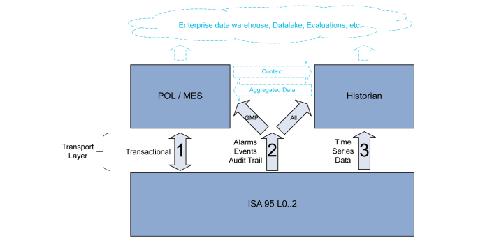
1. Communication with a POL (often MES or similar)
Communication with a POL is characterized by a bidirectional and transactional communication of data sets. These are often planned and part of the programming/recipe on both levels. Examples include the start and end of a batch where set values and batch-specific data is sent to L2, and the results of the batch are sent back to the MES once the batch is finished. It may also include phase start/result time stamps and In Process Control (IPC) signals. Typically, all data that is exchanged is GMP relevant.
2. Alarms, Events, Audit Trails Sent to POL and/or Historians
Characterized by event driven, unplanned or only partly planned, and unidirectional communication, these typically include GMP and non-GMP alarms, events, and audit trail entries recorded in L2.
3. Time Series Data
Typically, sensor or counter values are recorded at defined intervals into an historian or similar system that is specifically designed to work with larger data volumes of time/value data pairs. This can be GMP relevant, like Critical Process Parameters (CPP), and non-GMP data, the latter, for example, used for process optimization or as Key Performance Indicators (KPIs).
Looking at the different natures of the channels, the requirements for the technical side of the interfaces are quite different. In order to meet the goal of designing something tangible in the given time frame the focus was set to Channel 1 (as shown in Figure 3.1), and Channels 2 and 3 were explicitly excluded.
3.1.3 Use Widely Available Vendor-Independent Standard Technology
OPC UA was chosen as the underlying technology as it provides significant benefits over vendor-specific and OPC Data Access (DA) based interfaces. Some of the benefits of OPA UA are:
- Semantic information modeling and data transport functionalities
- Platform independence
- Built-in security mechanisms
3.1.4 “Fail Fast”
In order to bring the developed concept into off-the-shelf products as well as actual production use immediately following the release of this paper, it is vital to verify the concept in the target development environments as soon as possible. This was done by early and excessive prototyping during the discussion phase.
As a result of prototyping, several changes were made to the concept during its creation.
3.1.5 Use-Case Independent, Machine-Type Independent
Most of today’s initiatives in the area of Plug & Produce build on standardization of specific interfaces. For example, many of the companion specifications for OPC UA are written for specific types of machines and standardize the interface (how) and data transmitted (what). This provides excellent interoperability and ease of integration across multiple vendors and requires very little engineering in the project and setup phases.
However, the pharmaceutical industry’s requirements such as data integrity, metadata, and ALCOA+ lie somewhat horizontal to these machine-type silos, applying to all types of machines, systems, devices, and instruments to be connected. Additionally, the number of different types of machinery is high, especially when looking at the big picture including chemical and biotechnology Active Pharmaceutical Ingredient (API) production, Oral Solid Dosage (OSD) production, (sterile) filling, as well as primary and secondary packaging. Given the timeline of this Working Group’s Workstream, it is obviously impossible to follow that approach, as the commonalities of, e.g., a bioreactor, a filling line, a blister line, and a tablet press are low.
The approach chosen is therefore a use-case and machine-type independent approach that focuses on an abstract concept of services and transactions as a way to transport any set of data, without defining the “what” by mandatory service or variable names or structures.
Thus, equipment vendors do not need to change their internal data model or any sequencing/programming. The only thing that changes is how data is communicated technically. This significantly lowers the cost of implementation in existing systems and increases acceptance of the concept by vendors.
It should be mentioned that the price that is paid for this flexibility is that Subject Matter Experts (SME) are still needed to do the integration on a business logic level (although the effort required is significantly lower) and that the goal of a cross-vendor exchangeability of production equipment is not fulfilled with this concept.
However, the concept is an excellent foundation on which to build additional harmonization, which then likely will require people with different skillsets. While this interface concept was designed by cross-industry IT and automation specialists, the future harmonization of an interface requires SMEs for specific machine types and processes.
3.2 Concept Cornerstones
The concept described in this paper assumes some key elements to provide maximum value.
3.2.1 Ownership
Currently, customers often define the interfaces for their equipment in a User Requirement Specification (URS) when they acquire new equipment. These interfaces are then custom programmed and tailored to fit each customer.
As a result, even if an equipment vendor ships two almost identical pieces of equipment to two different customers, they may have two largely different interfaces to L3. As a vendor, a rather large number of different interfaces need to be maintained and supported for several years, or even decades.
This Concept Paper proposes that vendors assume ownership of their interfaces and provide a best practice interface as a standard position in their offerings.
Due to the diversity of customers, culture, and industry branches, it will be difficult to provide a single interface that suits all customers. We suggest that vendors build a standard interface based on their project experience regarding reliability, common workflows, and requested functions. When it comes to data points, a good balance must be kept so as to provide enough data for the majority of customers without overloading the interface with everything that has been asked for in the past.
It is expected that the interface of a specific piece of equipment must be tweaked to meet an end-customer’s specific needs. However, an interface in which 95% is based on a template and 5% is custom will most certainly be favored over a 100% custom interface.
3.2.2 Machine Interface Self-introduction
Today’s approach to designing an interface includes the exchange of documents, as stated in Section 3.2.1, often written by customers. This is followed by labor- and time-intensive implementations on both the equipment and POL side. Documents are subject to interpretation and, together with the inevitable human mistakes, more often than not lead to incompatibilities detected fairly late in the project phase.
This Concept Paper proposes a machine-readable interface description provided by the machine vendor.
OPC UA provides all tools necessary to describe an interface and then transfer that description. We expect that the data in the OPC UA server of a piece of equipment depicts all aspects of the equipment’s interface to such an extent that the POL can read and “understand” the interface of the equipment. This includes all metadata associated with the interface, such as human-readable description of objects, unit of measure (UOM), acceptable ranges for numeric data, and significant digits for floating-point values.
3.2.3 “Shift Left”
Shift Left is:
An approach to software testing and system testing in which testing is performed earlier in the lifecycle (i.e. moved left on the project timeline). It is the first half of the maxim “Test early and often. 3
Applied to L2/3 integration, shift left does not only mean completing integration tasks as soon as possible in the project, but that these tasks start and finish earlier in the project timeline than is common today. This goes beyond interface testing as it includes, for example, batch recipe design and testing in POL.
A major project risk is the technical implementation of interfaces, which may be flawed on either side. As of today, these flaws are discovered only when the equipment and the POL instance are ready (usually on-site) and a connection is established. Often this is during Factory Acceptance Tests (FAT) or Site Acceptance Tests (SAT), when an issue found here has a direct impact on the project timeline and cost, with a high risk of impacting final qualification timing.
The idea of moving the integration test completely off the critical path seems unreachable in practice, but large portions of the tasks and risk mitigations can be moved to an earlier project phase, where enough time is left for fixing problems without impacting the overall project timeline.
This Concept Paper proposes to ship the equipment’s interface data model in the standardized OPC Nodeset2 XML format to the customer prior to the systems meeting on-site.
Conducting the integration test earlier in the project plan involves the nodeset. The “nodeset” is a representation of an OPC UA Information Model (virtually the address space of an OPC UA server) in an internationally standardized file format. Together with the machine interface self-introduction described in Section 3.2.2, all of the information needed to configure/program the “other” system (e.g., recipes in POL) is available. This allows for communication between systems to be tested before commissioning on-site. Additionally, it allows for accelerated configuration of the other system (e.g., recipe development and testing in POL), as human errors related to assumptions and interpretations of the interface configuration are reduced.
In order to test interactions between systems (e.g., recipes on POL side and an L2 system), a generic communication simulation tool can be developed. This tool would simulate the communication of a piece of equipment using its nodeset file. Such a tool would not be able to simulate actual behavior; instead it would require the user to enter data to be sent by the equipment’s simulation and manually check the successful use of that data in the target system. However, it would be able to simulate the complete technical interface and allow for verification of the adherence to the interface description provided by the vendor, including all metadata, completeness, and data types.
In subsequent tests with actual equipment, only its behavior, data sent, sequence of transactions, and timing will need to be verified, significantly reducing test and setup effort on-site.
3.2.4 “Start Easy”
As part of this transactional interaction between L2 and L3 concept, parts of OPC UA are used that are not available on every platform and where automation engineers on both layers, L2 and L3, do not have a lot of experience.
In order to keep the bar for adopting the concept as low as possible and allow for easy onboarding of engineers, multiple options are made available in some aspects. This way a vendor can start with a limited set of tools, gain experience and confidence, and then proceed with advanced functions that require the use of advanced features of OPC UA.
3.3 Business Objects
The concept for a transactional interface introduces an abstract interface meta model (Figure 3.2):
- A unit provides one or many services
- A service provides one or many transactions
- A transaction transports one undividable set of data (the “payload”)
Figure 3.2: Business Objects
3.3.1 Unit
A unit is an entity that communicates with the POL. It can be a module as part of a larger setup, or the larger setup itself, for example, if controlled by a line management system or SCADA, and can provide an arbitrary number of services based on the functionality and the functional distribution of the two systems (Figure 3.3). For better human readability of the OPC UA server structure, the services are organized in one or more folders. The unit can provide services to multiple clients. If different clients should only access services specific to them, one folder per client can be published.
Figure 3.3: IspeUnitType

Multiple units can be exposed on or aggregated in one OPC UA server.
3.3.2 Service
A service is a function that the equipment provides with which the POL interacts (Figure 3.4). Often a service is started by the POL and returns results when it terminates. A service can have an arbitrary run time, all the way from seconds to several months.
Figure 3.4: IspeServiceType
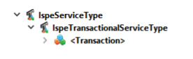
The number, name, and function of a service may be freely defined by the equipment vendor.
ISA 88 4 phases can be mapped to the services defined in this paper:
- An individual ISA 88 4 phase can be mapped to a service, e.g., CIP, wash, fill, or sterilize
- Multiple ISA 88 4 phases can be combined and mapped to one service, e.g., a “run” service
- Services that do not map to an ISA 88 phase 4 can also be published, e.g., momentary functions such as pressure release
A service can publish its status as a state machine. Note that this depicts the status of the service, not the status of the unit, as those might be different. Also note that the data transfer is technically independent of the state machine (Section 3.3.3).
3.3.3 Transaction
A transaction is an atomic (undividable) transport of a payload between two systems, such as, sending batch-specific parameters from the POL to L2 before a batch starts or the return of the data results when a batch ends. The same transaction can be used/occur multiple times during the execution of a service, for example, IPC-ready notifications. The interface should be designed in a way that a single transaction finishes within one second (network hiccups excluded).
A service can provide an arbitrary number of transactions.
A transaction always contains an OPC UA method of the name “Transaction.” Data transfer in both directions can be controlled via variables that are part of the transaction object and thus, are independent of the services’ or units’ state machine.
The processes seen in pharmaceutical production are quite heterogeneous and, in many cases, data transfer is neither bound to a start or end of a service or to an actual state change of the unit or service. One example is automatic IPC outlets in packaging where the POL is informed about every package that is pushed out for manual inspection during regular operation.
Consequently, this Concept Paper does not impose any restrictions as to which transactions are available. A machine vendor can freely design which transactions are available at any given point in time and state. This provides flexibility, e.g., accepting or sending data even in a running state if that is feasible in the context.
This Concept Paper defines three types of transactions: In-, InOut- and Out-Transactions (Figure 3.5).
Figure 3.5: ISPETransactionType and Subtypes
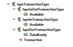
3.3.3.1 InTransactionType
An InTransaction is used to transfer one set of data to the equipment, e.g., from the POL to an L2 system. The equipment confirms the success of the transaction but does not transfer any payload (i.e., any type of business result data) back to the calling system.
An InTransaction can publish a Boolean variable Available to indicate that the transaction can be called.
3.3.3.2 InOutTransactionType
An InOutTransaction is used to transfer one set of data to the equipment, e.g., from the POL to an L2 system, and return another set of business-relevant data back to the calling system. From a technical perspective, this results in the OPC UA method of such a transaction having both input and output arguments that carry business data.
Note: The maximum expected time for a transaction to finish is 1 s. If that cannot be guaranteed, a combination of an InTransaction and an OutTransaction should be used.
An InOutTransaction can also publish a Boolean variable Available to indicate that the transaction can be called.
3.3.3.3 OutTransactionType
An OutTransaction is used to transfer one set of data from the equipment, e.g., from an L2 system to a POL.
An OutTransaction must have a Boolean variable DataReady that indicates that this transaction should be called to fetch the associated data from the equipment. After the call of the transaction’s OPC UA method, DataReady must be set back to false by the equipment. The calling system subscribes to the DataReady variable of an OutTransaction to be notified if a transaction is requested. Polling DataReady is also possible.
3.3.4 Transaction Results
Transactions must indicate whether they have been successful. Transactions can fail on two different levels: the transport logic or the business logic.
Failures on the transport level are detected by the OPC UA framework. They include issues such as a broken network connection, nonexistent methods, or wrong arguments or types. L2 will come back with a standard OPC UA error code. Depending on the code, the POL may do automatic retries on specific codes (e.g., network down). The return code of the method is used to indicate this type of failure, possible values of which are provided by the OPC specification.
Failing on the business level means that the method call itself has technically succeeded but the command cannot be executed by the receiver. This may be due to wrong parameters or parameter-combinations passed, e.g., 1,000,000 rpm for the speed or a nonexistent recipe ID. The method call will return with an “OK” OPC UA status code but provides information in the return arguments of the method. Ideally the information is human readable and gives end users an idea of where the issue might be, e.g., “Recipe parameter ‘Speed’ is out range: 1,000,000.” In these cases, the method should return with an “OK” code and use an output argument to describe the failure to the calling system.
If the environment supports structured types, the provided data type IspeTransactionResultType should be used, see Sections 3.3.5 and 5.2.1. If the environment does not support structured types, the components of IspeTransactionResultType can be added as individual output arguments in the method.
3.3.5 Data Types
In order to fulfill the requirements of a regulated industry (e.g., ALCOA+), specific structured data types are defined. This refers to guidance 5,6, 7 requiring that metadata be attached to the data at all times, and focuses on adding information regarding user, date and time of data acquisition, and adding a UOM, and actual precision to floating-point values.
Not all metadata is relevant for all use cases. As major platforms do not yet support optional components in data types, all components are marked as mandatory.
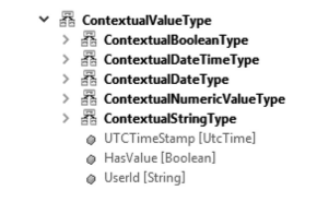
The abstract ContextualValueType is derived from the OPC UA Structure type. It provides the following attributes (as shown in Figure 3.6):
- UTCTimeStamp – Time when an individual value was generated
- HasValue – Indicates if the value is valid or empty (i.e., if it is null)
- UserId – User associated with the generation of the individual value
Figure 3.6: ContextualValueType and Its Basic Subtypes
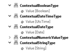
To associate this information with an actual value, a subtype of ContextualValueType must be used (see Figures 3.6 and 3.7). The subtypes for Boolean, DateTime, Date, and String add a Value of the respective type (Figure 3.7).
Figure 3.7: Basic Subtypes of ContextualValueType
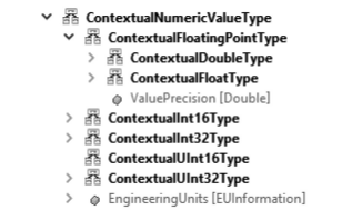
The abstract subtype ContextualNumericType adds a UOM or “EUInformation” to numeric data (Figure 3.8). All vendors are encouraged to send the UOM on outgoing data and verify the UOM on incoming data to follow the metadata requirements, and to enable systems to check the UOM versus specification and detect mismatches.
It is explicitly not expected that any sort of unit conversion will be calculated by either system. Upon detection of a unit mismatch, it is sufficient to raise an error and require manual intervention. When numerical values are used to transfer data that does not have a UOM by its nature, e.g., a RecipeNumber, the UOM should be left empty.
The abstract subtype ContextualFloatingPointType adds a ValuePrecision that indicates the number of significant fractional digits (Figure 3.8).
Figure 3.8: Subtypes of ContextualNumericValueType and ContextualFloatingPointType
All subtypes of ContextualNumericValueType and ContextualFloatingPointType also add a Value that all contextual information is related to (Figure 3.9).
Figure 3.9: Values of Subtype ContextualFloatingPointType
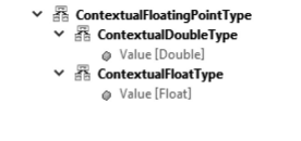
Figure 3.10: IspeTransactionResultType
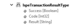
Per Section 3.3.4, a transaction’s OPC UA method should return one output argument of type IspeTransactionalResultType to provide feedback on the method calls’ success with regard to its business function (Figure 3.10). This provides the following attributes:
- Success – Indicates if a transaction was successful from a business perspective
- Code – Optional vendor-specific code to provide detailed information on a transaction
- Result – Optional text that provides more information on a transaction in a human-readable form
3.3.6 Arguments of a Transaction’s Method
Arguments of a transaction’s method can have any combination of the following data types:
- Standard OPC UA data types (e.g., Int32, double)
- Contextual data types per Section 3.3.5
- Custom structured types containing only standard OPC UA data types and/or contextual data types per Section 3.3.5
Whenever the environment supports structured types, vendors are encouraged to use the contextual types, and provide and check metadata wherever applicable. Using the OPC UA simple types should only be a fallback scenario.
Note that each transaction’s method should additionally have one output argument of type IspeTransactionResultType.
3.4 Metadata
One important part of this Plug & Product concept is the use of metadata, namely:
- Data Model Metadata: support of configuration efforts on calling systems, e.g., Master Batch Record (MBR) creation in the POL
- Payload Metadata: correct exchange of data during system runtime
3.4.1 Data Model Metadata
One aim of this team is to give equipment vendors the capability to provide self-describing interfaces to others. The ultimate benefit of a self-describing interface is a reduced effort in manual system configuration and reduced documentation outside the interface itself.
The unit/service/transaction hierarchy already provides the structure of an interface. On top of that, a description of the input and output arguments of a transaction’s method is needed. This includes a human-readable description of the arguments’ purposes as well as attributes, i.e., metadata. This metadata includes UOM, ranges, and precision. In this sense, it is the static metadata of the interface: it does not change during regular operation.
OPC UA provides a mechanism to describe a transaction’s method’s arguments in the address space of the equipment’s OPC UA server. The mechanism works by adding more nodes and references to an equipment’s address space. These references link methods’ arguments to the additional nodes. See Section 5.2.5 for further details.
3.4.2 Payload Metadata
As opposed to the data model metadata described in Section 3.4.1, the values of metadata transmitted during a transaction (the payload) are dynamic, i.e., not known previously.
Payload metadata is transferred by using the ContextualDataTypes (Section 3.3.5). The purpose of those data types is to follow the various data integrity guidelines by attaching relevant metadata to transferred data at all times. This allows the receiving system to:
- Unambiguously interpret data
- Safely and completely record or process data
- Double check against the specification (e.g., UOM)
3.5 Versioning
This interface concept is planned as an iterative and evolutionary process, therefore a versioning of not only documents but also of the interface itself is necessary. Nodesets of OPC UA information models have a built-in version information that is also exposed in an OPC UA server’s address space. This capability is suitable for versioning the interface meta model introduced in this concept.
A hierarchical versioning with three levels is defined: major version/minor version/patch. It is strongly recommended that client systems check the compatibility of the interface meta model version with the interface meta model version that the client system supports.
Clients can assume compatibility if the patch level of the server is higher than that of the client system.
3.6 Required OPC UA Parts
As opposed to the classic-OPC approach of just exposing data tags that can be read and written, the OPC UA specification provides a multitude of excellent and advanced functions. However, not all aspects of the specification are widely available in today’s development environments. In order to create a concept that is immediately usable by a large number of vendors, the Working Group only used the OPC UA aspects the team considers to be broadly available or that are clearly in development. Nevertheless, we understand that as of today not all environments support the concept.
In this concept OPC UA methods are used to transfer data between two systems. This functionality of OPC UA has been chosen as it provides significant benefits over the classical tag-based communication when it comes to transactional data transfer of structured data such as:
- Ease of ensuring data integrity
- Built-in transactional safety
- Elimination of handshakes
- Vast improvement of detectability when mistakes are made in configuration/changes
- Reduced test effort
As a minimum, this concept requires the following OPC UA aspects:
- Variables
- Subscription to variable (server)
- Usage of the object types provided as part of this paper
- Method calls
To create the maximum value of this concept, the following OPC UA aspects are also required:
- Structured data types
- Passing and receiving structured types as arguments to/from methods
- Reference type “HasArgumentDescription”
- Optional members in structured types
4 Conclusion
In this Concept Paper, the ISPE Pharma 4.0 Plug & Produce Working Group presents a solution for one of the many functionalities required to achieve Plug & Produce capability of systems. This functionality is a transactional interaction between ISA95 Level 2 and Level 31 systems. From a technical perspective, our solution introduces an OPC UA information meta model that enables the design of an interface between ISA Level 2 and Level 3. Said interface is modeled based on services and individual transactions. Data integrity has been taken into account, so attaching information such user IDs, timestamps, and UOM are possible.
From an organizational perspective, we propose that the ownership of a system’s interface is transferred to the system vendor. This allows for an extended use of templating mechanisms for Level 2 vendors and implementation of auto-config features for Level 3 vendors, potentially freeing up heavily taxed resources in automation and IT departments. In combination with properly planned workflows, it also serves as an enabler for conducting many configuration and test efforts earlier than typical in a project timeline, moving them off the critical path.
All in all, we believe that this solution, just as any standardization, has the potential to reduce project engineering times, costs, and late project risks for all parties involved. We feel this will off-set the price of a one-time effort for system vendors when first creating an interface template and implementing required functionality as well as changing internal company workflows.
5 Annex: Detailed Concept
This annex contains a more formalized description of the interface meta model defined in Chapter 3, and begins by describing how to structure the address space of an OPC UA server to expose the transactions available, and finishes with how the payload of a transaction may look like.
5.1 Exposing the Interface
As explained in Sections 3.3.1 through 3.3.3, it is proposed that an interface is structured in a Unit – Services – Service X – Transaction Y – Method Z hierarchy.
5.1.1 IspeUnitType
Per Section 3.3.1, a unit is a base business entity that provides services that may be used. Within the unit’s OPC UA server, there must be a root node of the type IspeUnitType holding all information related to that unit. IspeUnitType is defined in Table 5.1.
| Attribute | Value | ||||
|---|---|---|---|---|---|
| BrowseName | IspeUnitType | ||||
| IsAbstract | False | ||||
| References | NodeClass | BrowseName | DataType | TypeDefinition | ModelingRule |
| Subtype of BaseObjectType | |||||
| HasComponent | Object | Services | -- | FolderType | Mandatory |
Services is a folder that holds all the services that the unit makes available. There must be at least one instance of this folder. The number of services that may be exposed is arbitrary, i.e., ranges from zero to as many as the unit’s computational resources support.
5.1.2 Services
Within an IspeUnitType instance, the Services folder holds all the services that this unit exposes. All exposed services must be one subtype of IspeServiceType.
5.1.2.1 IspeServiceType
All services that a unit exposes must be a subtype of IspeServiceType. IspeServiceType is defined in Table 5.2.
| Attribute | Value | ||||
|---|---|---|---|---|---|
| BrowseName | IspeServiceType | ||||
| IsAbstract | True | ||||
| References | NodeClass | BrowseName | DataType | TypeDefinition | ModelingRule |
| Subtype of BaseObjectType | |||||
| HasComponent | Object | Services | -- | StateMachineType | Optional |
ServiceState is an optional means of exposing what state a specific service is in. Any state machine that is of type StateMachineType or one of its subtypes may be used to model a services state. StateMachineType is defined in OPC 10000-5 8.
5.1.2.2 IspeTransactionalServiceType
When a unit has a service that requires a transactional transfer of information, an instance of IspeTransactionalServiceType must be used. IspeTransactionalServiceType is defined in Table 5.3.
| Attribute | Value | ||||
|---|---|---|---|---|---|
| BrowseName | IspeTransactionalServiceType | ||||
| IsAbstract | False | ||||
| References | NodeClass | BrowseName | DataType | TypeDefinition | ModelingRule |
| Subtype of BaseObjectType | |||||
| HasComponent | Object | <Transaction> | -- | IspeTransactionalType | OptionalPlaceholder |
<Transaction> is a placeholder for the transactions that a service offers. There is no lower or upper limit to the number of transactions that a transactional service may have. All transactions must be a subtype of IspeTransactionType. IspeTransactionType and its subtypes are defined in Section 5.1.3.
5.1.3 Transactions
Each instance of IspeTransactionalServiceType may have an arbitrary number of transactions associated with it. Each transaction must be an instance of a subtype of IspeTranscationType.
5.1.3.1 IspeTransactionType
All transactions of a transactional service must of one of the subtypes of IspeTransactionType. IspeTransactionType is defined in Table 5.4.
| Attribute | Value | ||||
|---|---|---|---|---|---|
| BrowseName | IspeTransactionType | ||||
| IsAbstract | True | ||||
| References | NodeClass | BrowseName | DataType | TypeDefinition | ModelingRule |
| Subtype of BaseObjectType | |||||
| HasComponent | Object | Transaction | -- | -- | MandatoryPlaceholder |
The Transaction Method is used to exchange the transactions data. The semantic of the Transaction Method changes based on the subtypes of IspeTransactionType. Per Section 3.2.1, both the number, semantic, and data of each transaction is defined by the system vendor and is explicitly not part of this concept.
5.1.3.2 IspeInTransactionType
Transactions of the type IspeInTransactionType are used when a business data payload needs to be transmitted to the unit and no business data payload needs to be extracted from the unit. IspeInTransactionType is defined in Table 5.5.
| Attribute | Value | ||||
|---|---|---|---|---|---|
| BrowseName | IspeInTransactionType | ||||
| IsAbstract | False | ||||
| References | NodeClass | BrowseName | DataType | TypeDefinition | ModelingRule |
| Subtype of BaseObjectType | |||||
| HasComponent | Variable | Available | Boolean | BaseDataVariableType | Optional |
The Transaction Method defined in IspeTransactionType is called to transmit a business payload to the unit by means of the method’s input arguments. Section 5.2 explains how to structure that business payload.
Available is used to indicate whether this transaction is currently available for use, i.e., whether the transactions Transaction Method is ready to be called by an OPC UA client at this time. Note that technically it is possible to call the Transaction Method even if the value of Available is false. The method call may fail on a business logic level and the method’s output arguments may indicate as such. Section 5.2 explains how to structure the method’s payload, i.e., input and output arguments, both business and technical.
5.1.3.3 IspeInOutTransactionType
Transactions of the type IspeInOutTransactionType are used when a business data payload needs to be transmitted to the unit and a business data payload needs to be extracted from the unit in one transaction. This transaction type is to be used when the expected method return time is < 1 s. IspeInOutTransactionType is defined in Table 5.6.
| Attribute | Value | ||||
|---|---|---|---|---|---|
| BrowseName | IspeOutTransactionType | ||||
| IsAbstract | False | ||||
| References | NodeClass | BrowseName | DataType | TypeDefinition | ModelingRule |
| Subtype of BaseObjectType | |||||
| HasComponent | Variable | Available | Boolean | BaseDataVariableType | Optional |
The Transaction Method defined in IspeTransactionType is called to transmit a business payload to the unit by means of the method’s input arguments and extract a business payload from the unit by means of the method’s output arguments. See Section 5.2 for instructions on how to structure that business payload.
Available is used to indicate whether this transaction is currently available for use, i.e., whether the transaction’s Transaction Method is ready to be called by an OPC UA client at this time. Note that technically it is possible to call the Transaction Method even if the value of Available is false. The method call may fail on a business logic level and the method’s output arguments may indicate as such. See Section 5.2 for instructions on how to structure the method’s payload, i.e., input and output arguments, both business and technical.
5.1.3.4 IspeOutTransactionType
Transactions of the type IspeOutTransactionType are used when a business data payload needs to be extracted from the unit without first transmitting business data to the unit in the same transaction. IspeOutTransactionType is defined in Table 5.7.
| Attribute | Value | ||||
|---|---|---|---|---|---|
| BrowseName | IspeOutTransactionType | ||||
| IsAbstract | False | ||||
| References | NodeClass | BrowseName | DataType | TypeDefinition | ModelingRule |
| Subtype of BaseObjectType | |||||
| HasComponent | Variable | DataReady | Boolean | BaseDataVariableType | Optional |
The Transaction Method defined in IspeTransactionType is called to extract a business payload from the unit by means of the method’s output arguments. See Section 5.2 for instructions on how to structure that business payload.
DataReady is used to indicate whether the data that is to be transmitted in this transaction is ready for extraction from the unit. Note that it is technically possible to call the Transaction Method even if the value of DataReady is false. The method call may fail on a business logic level and the method’s output arguments may indicate as such. See Section 5.2 for instructions on how to structure the method’s payload, i.e., input and output arguments, both business and technical.
5.2 The Payload
The core of information transfer in this transactional interface is the use of an OPC UA method. This Concept Paper defines a meta model to structure the information to be transmitted. The information itself must be defined by the unit’s vendor. This section focuses on that meta model.
No limit is imposed on the number of vendor-defined input or output arguments that a method may utilize. Vendors are encouraged to return one argument of type IspeTransactionalResultType. Each argument type may be a simple data type, a ContextualValueType, or a custom data type.
5.2.1 IspeTransactionResultType
A transaction may succeed or fail on a technical and/or business level. All things technically related are specified in the base set of OPC UA specifications and are not covered here.
To indicate the success or failure of the business part of a transaction, each method of each transaction must have one output argument of the type IspeTransactionResultType. It provides the vendor of a unit the opportunity to submit details on the business part of the transaction to the interacting other system. IspeTransactionResultType is defined in Table 5.8.
| Value | Description | |
|---|---|---|
| Success | Boolean | |
| Code | Int32 | |
| Result | String |
Success indicates whether the business part of a transaction was successful or not.
Code can be used to transmit a vendor-specific code to provide more detailed information about the result of a specific transaction.
Result is human-readable information about the results of a specific transaction.
5.2.2 Standard Data Types
Arguments may be of a standard OPC UA data type. These are limited to common data types present in most programming languages:
- String
- Boolean
- Integers, both signed and unsigned, in 16- and 32-bit length
- Floating-point numbers Float and Double
- DateTime format UTC
5.2.3 ContextualValueTypes
Arguments may also be of a ContextualValueType. These are types that allow a time stamp and a user ID to be associated with a specific value. They also present the opportunity to explicitly specify if a variable has a value or is empty. All ContextualValueTypes are structured data types.
5.2.3.1 ContextualValueType
ContextualValueType serves as a parent type to all other ContextualValueTypes. An actual value that this information is associated with is added by means of subtyping. ContextualValueType is abstract, meaning it cannot be instantiated. ContextualValueType is defined in Table 5.9.
| Value | Description | |
|---|---|---|
| UTCTimeStamp | Time Stamp in UTC | |
| HasValue | Boolean set to false if value is NULL | |
| UserId | String |
UTCTimeStamp is the UTC that is associated with the Value of each ContextualValueType.
HasValue defines whether Value has content or is null.
UserId is the ID of the user that is associated with the Value of each ContextualValueType.
5.2.3.2 ContextualBooleanType
ContextualBooleanType is used when a time stamp, user, and “HasValue” information must be associated with a Boolean variable. ContextualBooleanType is defined in Table 5.10.
| Value | Description | |
|---|---|---|
| Value | Boolean |
Value is the value associated with UTCTimeStamp, HasValue, and UserId of ContextualValueType.
5.2.3.3 ContextualDateTimeType
ContextualDateTimeType is used when a time stamp, user ID, and “HasValue” information must be associated with a DateTime variable. ContextualDateTimeType is defined in Table 5.11.
| Value | Description | |
|---|---|---|
| Value | Time Stamp in UTC |
Value is the value associated with UTCTimeStamp, HasValue, and UserId of ContextualValueType.
5.2.3.4 ContextualDateType
ContextualDateType is used when a time stamp, user ID, and “HasValue” information must be associated with a Date variable. ContextualDateType is defined in Table 5.12.
| Value | Description | |
|---|---|---|
| Value | Date |
Value is the value associated with UTCTimeStamp, HasValue and UserId of ContextualValueType.
5.2.3.5 ContextualStringType
ContextualStringType is used when a time stamp, user ID, and “HasValue” information must be associated with a String variable. ContextualStringType is defined in Table 5.13.
| Value | Description | |
|---|---|---|
| Value | String |
Value is the value associated with UTCTimeStamp, HasValue, and UserId of ContextualValueType.
5.2.3.6 ContextualNumericValueType
ContextualNumericValueType is the parent type for types that are used when a time stamp, user ID, and “HasValue” information must be associated with a numeric variable. ContextualNumericValueType is abstract, meaning it cannot be instantiated. ContextualNumericValueType is defined in Table 5.14.
| Value | Description | |
|---|---|---|
| EngineeringUnits | EUInformation |
EngineeringUnits is the unit of value associated with UTCTimeStamp, HasValue, and UserId of ContextualValueType.
5.2.3.7 ContextualInt16Type
ContextualInt16Type is used when a time stamp, user ID, and “HasValue” information must be associated with a 16-bit integer variable. ContextualInt16Type is defined in Table 5.15.
| Value | Description | |
|---|---|---|
| Value | Int16 |
Value is the value associated with UTCTimeStamp, HasValue, and UserId of ContextualValueType, as well as EngineeringUnits of ContextualNumericValueType.
5.2.3.8 ContextualInt32Type
ContextualInt32Type is used when a time stamp, user ID, and “HasValue” information must be associated with a 32-bit integer variable. ContextualInt32Type is defined in Table 5.16.
| Value | Description | |
|---|---|---|
| Value | Int32 |
Value is the value associated with UTCTimeStamp, HasValue, and UserId of ContextualValueType as well as EngineeringUnits of ContextualNumericValueType.
5.2.3.9 ContextualUInt16Type
ContextualUInt16Type is used when a time stamp, user ID, and “HasValue” information must be associated with a 16-bit unsigned integer variable. ContextualUInt16Type is defined in Table 5.17.
| Value | Description | |
|---|---|---|
| Value | UInt16 |
Value is the value associated with UTCTimeStamp, HasValue, and UserId of ContextualValueType as well as EngineeringUnits of ContextualNumericValueType.
5.2.3.10 ContextualUInt32Type
ContextualUInt32Type is used when a time stamp, user ID, and “HasValue” information must be associated with a 32-bit unsigned integer variable. ContextualUInt32Type is defined in Table 5.18.
| Value | Description | |
|---|---|---|
| Value | UInt32 |
Value is the value associated with UTCTimeStamp, HasValue, and UserId of ContextualValueType as well as EngineeringUnits of ContextualNumericValueType.
5.2.3.11 ContextualFloatingPointType
ContextualFloatingPointType is the parent type for types that are used when a time stamp, user, “HasValue,” and engineering unit information must be associated with a floating-point variable. ContextualFloatingPointType is abstract, meaning that it cannot be instantiated. ContextualFloatingPointType is defined in Table 5.19.
| Value | Description | |
|---|---|---|
| ValuePrecision | Double |
ValuePrecision is the number of significant fractional digits of the value associated with UTCTimeStamp, HasValue, and UserId. If all available digits are to be considered, ValuePrecision must be set to “-1”.
5.2.3.12 ContextualDoubleType
ContextualDoubleType is used when a time stamp, user ID, and “HasValue” information must be associated with a double variable. ContextualDoubleType is defined in Table 5.20.
| Value | Description | |
|---|---|---|
| Value | Double |
Value is the value associated with UTCTimeStamp, HasValue, and UserId of ContextualValueType as well as EngineeringUnits of ContextualNumericValueType and ValuePrecision of ContextualFloatingPointType.
5.2.3.13 ContextualFloatType
ContextualFloatType is used when a time stamp, user ID, and “HasValue” information must be associated with a float variable. ContextualFloatType is defined in Table 5.21
| Value | Description | |
|---|---|---|
| Value | Float |
Value is the value associated with UTCTimeStamp, HasValue, and UserId of ContextualValueType as well as EngineeringUnits of ContextualNumericValueType and ValuePrecision of ContextualFloatingPointType.
5.2.4 Custom Data Types
A unit’s vendor may define their own structured data types. These custom structured data types may not be nested, i.e., custom structured data types may only contain variables that are an arbitrary mixture of the types listed/defined in Sections 5.2.2 and 5.2.3.
An exemplary definition of custom data type is shown in Table 5.22.
| Value | Description | |
|---|---|---|
| <Custom Variable Name 1> | ContextualFloat | |
| <Custom Variable Name 2> | ContextualFloat | |
| <Custom Variable Name 3> | String |
5.2.5 HasArgumentDescription
Amendment 3: Method Metadata to version 1.04 of the OPC UA specifications 9 defines a means of exposing, within the address space of an OPC UA server, a description of a method’s arguments, e.g., its engineering units and ranges.
Essentially, an additional variable node is created for each input and output argument of a method. The BrowseName of the node must be the same as the name and type of the corresponding argument. The method-node is then linked to each additional node by means of a HasArgumentDescription reference.
Depending on the type of argument, the reference points to a variable of standard OPC UA types or to a custom variable type.
This concept supports the following variable types for the description of arguments (Figure 3.11): BaseAnalogType and its subtypes AnalogItemType, AnalogUnitType and AnalogUnitRangeType.
Figure 3.11: Variable Type BaseAnalogType
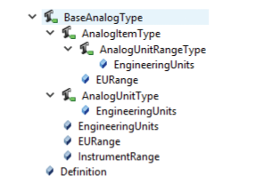
The metadata variables are mostly self-explanatory:
- EngineeringUnits adds a UOM
- EURange adds the valid range of the argument
- ValuePrecision adds the number of significant fractional digits as described in the ContextualDataTypes above
In the following example, the Start transaction requires an input argument of the standard type Int32 with the name Time (see Figure 3.12).
Figure 3.12: Metadata for Standard OPC UA Data Type Arguments
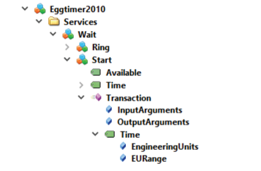
The method Transaction is linked to the variable matching the name of the argument it describes, in this case Time. The variable here is of the type AnalogUnitRangeType that brings sub-variables for the UOM EngineeringUnits and the valid Ranges EURange. The Description property of the Time variable should be used to describe the purpose of the argument to the client application in a human-readable form to support recipe creation and understandability of the interface without additional documentation.
If custom structured types are used as arguments, the same principal is applied. The variable linked to the method must have the same structure as the argument type itself.
Figure 3.13: Metadata for Structured Data Type Arguments
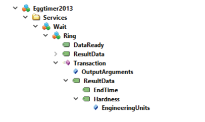
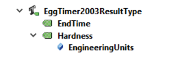
In Figure 3.13, the output argument of the Ring transaction is of the custom data type Eggtimer2003ResultType (Figure 3.14) that consists of two components: EndTime and Hardness, which again are structured types, see above ContextualDataTypes (Section 3.5.5).
Figure 3.14: Example – Custom Result Data Type

Providing metadata for arguments of structured types can be achieved in two ways.
The first option is to manually recreate the structure of the data type using variables with identical names and structure.
The second option is to create a custom variable type Eggtimer2003ResultType with the identical names and structure of the data type. The EndTime Variable is of the standard OPC UA Data Type Int32 and does not have any substructure. Only the Description property is used to describe the meaning of the argument. The Hardness variable is of the type AnalogUnitType, which on top of the description also publishes the UOM in which the hardness is returned to the client.
Figure 3.15: Example – Custom Result Variable Type
In the example in Figure 3.15, an instance of the custom variable type with the name as the argument (here: ResultData) is referenced by using the HasArgumentDescription reference by the method.
Important notes:
- In all cases, the variables are exclusively used as containers to store and publish the metadata of the interface in the data model. The actual value of the variables is never to be used to transfer actual data.
- Clients can safely rely on metadata not to change during regular operation. A client is explicitly not required to subscribe or poll these data for changes. If metadata should be changed (e.g., a UOM goes from liter to kilogram), this is considered an interface change and can be expected to be run under change control.
6 Acronyms and Abbreviations
| ALCOA | Acceptable, Legible, Contemporaneous, Original, Accurate (ALCOA) with the addition of Complete, Consistent, Enduring, Available |
| API | Active Pharmaceutical Ingredient |
| CIP | Clean in Place |
| CPP | Critical Process Parameters |
| DA | Data Access |
| FAT | Factory Acceptance Tests |
| GMP | Good Manufacturing Practice |
| GxP | Good “x” Practice |
| IPC | In Process Control |
| IT | Information Technology |
| KPI | Key Performance Indicators |
| MBR | Master Batch Record |
| MES | Manufacturing Execution System |
| MVP | Minimum Viable Product |
| OPC | Open Platform Communication |
| OSD | Oral Solid Dosage |
| POL | Process Orchestration Layer |
| SAT | Site Acceptance Tests |
| SCADA | Supervisory Control and Data Acquisition |
| SME | Subject Matter Experts |
| UOM | Unit of measure |
| URS | User Requirement Specification |
| UTC | Coordinated Universal Time |
Limitation of Liability
In no event shall ISPE or any of its affiliates, or the officers, directors, employees, members, or agents of each of them, or the authors, be liable for any damages of any kind, including without limitation any special, incidental, indirect, or consequential damages, whether or not advised of the possibility of such damages, and on any theory of liability whatsoever, arising out of or in connection with the use of this information.
© 2021 ISPE. All rights reserved.
All rights reserved. No part of this document may be reproduced or copied in any form or by any means – graphic, electronic, or mechanical, including photocopying, taping, or information storage and retrieval systems – without written permission of ISPE.
All trademarks used are acknowledged.
Acknowledgements
By the ISPE Pharma 4.0 Plug & Produce Working Group
This Concept Paper represents the outcome of work done by the members of Workstream 1 – Connectivity – of the ISPE Pharma 4.0 “Plug and Produce” Workgroup as well as experiences and input from the individuals listed and does not reflect the views of any one individual or company.
Document Authors
Björn Gerber, Pharmaplan, Germany
Helge Traut, Takeda, Switzerland
Henrik Stellmann, Körber (former Werum), Germany
Jouni Aro, Prosys OPC, Finland
Reviewers
Particular thanks go to the following for their support and review of this Concept Paper:
Rod Hoffman, AstraZeneca, USA
Stefan Krauss, Siemens AG, Germany
Giuseppe Menin, Copa Data, Italy
Barry Stewart, AstraZeneca, USA
Additional Members of Workstream 1 – Connectivity – of the ISPE Pharma 4.0 “Plug and Produce”:
Holger Angele, Uhlmann, Germany
Hanna Basilewitsch, Körber (former Werum), Germany
Marco Bellentani, MG2 S.r.l., Italy
Michael Carstens, B&R Industrial Automation GmbH, Germany
Giuseppe Di Vietri, Merck KGaA, Italy
Florian Hinrichsen, Körber (former Werum), Germany
Monika Katoch, Atec Pharmatechnik GmbH, Germany
Konstantin Klein, B&R Industrial Automation GmbH, Austria
Heiko Kröber, onoff it-solutions GmbH, Germany
Volker Lüdeling, onoff it-solutions GmbH ,Germany
Christian Miguel-Langstrof, Pharmaplan, Germany
Richard Pineo, Vertex Pharmaceuticals, USA
Colin Potter, GlaxoSmithKline, United Kingdom
Fabian Rauer, onoff it-solutions GmbH, Germany
Klaus Sauermann, Körber (former Werum), Germany
Kai Schnellecke, Siemens AG, Germany
Nicolas Teissie, Siemens AG, France
Jan Wrage, Atec Pharmatechnik GmbH, Germany
Sonny Zolota, Uhlmann, Germany
The team would also like to thank ISPE for technical writing and editing support by Jeanne Perez (ISPE Guidance Documents Technical Writer/Editor) and production support by Lynda Goldbach (ISPE Guidance Documents Manager).