Safeguarding Vial Container Closure Integrity: A Systematic Approach
Any systematic pharmaceutical engineering approach for ensuring vial container closure system (CCS) performance must include choosing qualified container closure system components, the proper pharmaceutical process setup, and applicable testing methods. Container closure integrity (CCI) is an essential part of container closure system performance. A holistic strategy is needed to qualify container closure system performance under the required temperature conditions during the entire product shelf life. To minimize potential safety risks and ensure the best container closure system performance, the strategy must balance and optimize many critical variables through a data-driven approach to informed decision-making.
Primary packaging plays a critical role in maintaining drug quality and full regulatory compliance throughout the product’s shelf life. A vial container closure system for pharmaceutical, biological, cell, and gene therapies must maintain container closure integrity to ensure that the drug products remain stable and free of contamination from microbial ingress. Pharmaceutical engineering for container closure system must include container closure system component qualification, a pharmaceutical process setup for assembling the container closure system, storing and shipping the pharmaceutical product through various conditions, and proper evaluation of the container closure system to ensure its container closure integrity throughout the entire sealed product shelf life.
Container Closure System Regulatory Compliance
Appropriate container closure system performance is mandatory before pharmaceutical products are made available for human use. Among the key guidance publications for container closure system qualification are US Pharmacopeia (USP) Chapter <1207>;1 US FDA guidance;2 EudraLex, Volume 4, Annex 1;3 and ICH Q5C.4 These guidance documents include general guidelines and various testing methods.
To ensure patient safety and meet regulatory requirements for container closure system, a number of factors must be addressed, including risks associated with gas and moisture ingress, changes in vacuum pressure, leakage, capping, sealing, visual inspection acceptance, and temperature cycling.
Gas and Moisture Ingress
Pharmaceutical products, including cell and gene therapy products and short-life biologics, may contain molecular structures or chemical function groups and fully functional cells that are sensitive to oxidization and pH value changes. Oxygen may cause oxidation in the product. Carbon dioxide (such as the dry ice used for storage and shipping) can be easily dissolved in solution and become carbonic acid, which can lower the solution’s pH. Some drugs can be sensitive to moisture, which causes drug degradation. Ingress of gases, such as oxygen or carbon dioxide, and moisture must be controlled according to drug sensitivity and specific product requirements. Additional protection can be achieved by filling the container closure system headspace with an inert gas, such as nitrogen.
Changes in Vacuum Pressure
The container closure system may have to go through the lyophilization process and may need to maintain a specific internal vacuum pressure level at cold temperatures over the product shelf life. This vacuum pressure level may be intentionally designed for the purpose of drawing a controlled liquid through a needle inserted into the vial container closure system at the moment of patient administration. If a vacuum is specified to aid in the reconstitution of a lyophilized product, the loss of that vacuum or a change in vacuum pressure could lead to incomplete reconstitution or extraction of the drug product, thereby delivering an inaccurate dose to the patient.
Leakage Control
Most pharmaceutical package types may display extremely low leakage flow through the gap that exists even between well-fitted closures.1 From the practical view of pharmaceutical engineering, a vial container closure system package should not permit leakage beyond the maximum allowable leakage limit (MALL)1 to maintain acceptable drug product sterility and stability. This limit is based on the actual drug packaging system and its specific requirements. To satisfy container closure integrity requirements, companies must use a systematic approach to minimize leakage that includes choosing an appropriate container closure system, qualifying compatible container closure system components, setting up a robust pharmaceutical process for assembling the container closure system, maintaining proper storage and shipping conditions to minimize the potential impact of cold temperature and duration, and establishing suitable testing methods for quantifying and ensuring container closure system quality during the sealed product shelf life. Prior to use, all individual components must be protected from improper storage and shipping conditions that could damage the parts.
![Figure 1: RSF and helium leak testing data for vial CCS using a 20 mm butyl elastomer stopper and a 10 mL glass vial fully filled with helium at ambient pressure, tested at ambient temperature through a vacuum chamber [8, 9]](/sites/default/files/2021-09/0921_PE_SO_TechZeng_01.jpg)
Capping, Sealing, and Temperature Cycling
A typical vial container closure system configuration has three major components: a vial, an elastomer stopper, and an aluminum seal with or without a flip-off button.5 Among these container closure system components, the elastomer stopper plays a critical role by deforming to seal the vial-stopper interface area either temporarily or permanently. From a pharmaceutical engineering point of view, the vial container closure system packaging includes both the selection of container closure system components and the capping process setup for delivering container closure system performance. Typically, the container closure system assembly is capped at room temperature. For a lyophilized product, the vial may be vacuumed to a pressure below the ambient pressure and may be filled with an inert gas (e.g., nitrogen) before being stoppered and capped.
The capped container closure system assembly may have to undergo required cold temperature cycles for processing, storage, and shipping. For example, it is common to store and ship some biological and cell and gene therapy products in the frozen state (e.g., in dry ice at –80°C or at cryogenic temperature below –150°C). These low-temperature cycles may have an adverse impact on container closure integrity performance6, 7 and the sealing performance of container closure systems in cold temperature conditions is important. Any container closure integrity breach could potentially lead to the ingress of oxygen, carbon dioxide, moisture, or microorganisms and, consequently, could risk the drug product integrity and stability depending on drug molecular structure sensitivity, potentially jeopardizing patient safety.
Because any container closure integrity breach may risk patient health, the components—elastomer stopper, vial, and aluminum seal—together with the capping process, must be properly selected, set up, and controlled to ensure acceptable container closure integrity performance under the required temperature conditions during the entire product shelf life. Container closure system qualification should occur with the desired component options or platforms that will be employed for the drug’s final presentation. It is necessary to look at the container closure system package in its entirety.
Residual Seal Force (RSF)
The container closure system components come together as the primary packaging system that provides a barrier to protect a sterile drug product from product loss and from microbial or environmental contamination. The elastomer stopper provides a significant amount of this protection, and factors affecting its performance are discussed here. One of the benefits of using an elastomer stopper is its ability to deform and form a sealed interface with another material, such as a glass or polymer vial. This ability can be adversely affected if the composition of the elastomer itself or the surface of the component is not pliable. To ensure acceptable container closure integrity, a vial container closure system must maintain adequate residual seal force (RSF), which is the force that an elastomer stopper flange exerts against the vial flange surface in a capped vial container closure system. Residual seal force is included in USP Chapter <1207> as a seal quality test for parenteral vials.1 The residual seal force within a container closure system is inherently time-dependent, decaying exponentially over time and eventually leveling off owing to elastomer stopper compression stress relaxation (CSR).8, 9 This is shown in the top graph of Figure 1, in which testing and modeling data are used to present residual seal force as a function of time. To ensure sufficient residual seal force throughout the entire product shelf life, it is important to use a qualified stopper together with a proper capping process setup.
Typically, stopper materials are made of elastomer compounds primarily composed of polymers and additives. These material ingredients are specifically chosen and engineered both for manufacturing processing purposes and to satisfy the requirements for end-product application performance. Elastomer polymer molecule structures may be linear, branched, cross linked, or networked, all of which affect the chemical, physical, and mechanical properties of the elastomer stopper,10, 11 resulting in both elastic and viscous resistance to compression.12, 13
Because any CCI breach may risk patient health, the components and capping process must be properly selected, set up, and controlled.
Compression Stress Relaxation
In effect, elastomer stoppers can partially retain the recoverable (elastic) strain energy, but they can also partially dissipate (viscous) energy if stopper compression is maintained after capping. Therefore, under constant compression, elastomer stoppers undergo compression stress relaxation (CSR). By following the Maxwell-Wiechert model of polymer structures and properties, a physical and mathematical model can be developed to describe elastomer compression stress relaxation under compression.12, 13
The top graph in Figure 1 provides an example from a case study to show residual seal force relaxation decay in testing and modeling data.8, 9 Figure 1 also demonstrates the relationship between residual seal force and the results of container closure integrity testing for helium leak up to one year after sealing. It clearly shows that residual seal force inherently undergoes time-dependent compression stress relaxation owing to the viscoelastic nature of the elastomer stopper materials. Typically, a high stopper compression percentage leads to high residual seal force. The degree of stopper compression stress relaxation could affect the ultimate sealing capability of the container closure system to meet container closure integrity requirements throughout the entire sealed drug shelf life. In general, as shown in Figure 1, a high residual seal force leads to relatively low helium leakage results, with tight statistical spreads for good container closure integrity performance, whereas low residual seal force results are associated with poor container closure integrity performance, causing relatively high helium leakage results, and large statistical spreads, increasing the risk of failing the maximum MALL.
Residual seal force relaxes over time because of the viscoelastic characteristic nature of the elastomer stopper materials. The magnitude and rate of residual seal force decay depend on the elastomer polymer’s molecular structure, formulation, and properties; the container closure system dimensions (stopper, vial, and aluminum seal); and the capping process setup. In fact, residual seal force decay can be engineered to a certain degree through the design of the elastomer molecule structure and by modifying the material properties for optimal container closure integrity. The resultant residual seal force relaxation decay has an impact on whether the container closure system can successfully maintain adequate container closure integrity throughout the entire sealed drug product shelf life. To ensure acceptable container closure integrity, proper stopper compression must be imposed by the capping process for maintaining acceptable residual seal force during the product shelf life.
Sealing Performance at Cold Temperature
Container closure integrity should be considered over the drug product’s shelf life, including when assessing transportation and storage conditions of the vial container closure system packaging system. Container closure integrity must be stable under the multitude of potential circumstances that a vial product might encounter over its shelf life. In cold temperature applications, the container closure system is typically assembled during a capping process at room temperature with the intent of obtaining sufficient residual seal force for acceptable container closure integrity at cold temperatures.
The assembled container closure system may need to withstand cold temperature conditions, per the requirements of drug processing or drug storage as well as shipping, and is typically then returned to room temperature for dosage injection. Container closure integrity may perform adequately at room temperature but be at risk at cold temperatures. For cold chain management, it is imperative to fully understand sealing performance changes related to time-temperature transitions and the subsequent impact of such changes on container closure integrity performance.
The sealing properties of the elastomer stopper are highly dependent on temperature, which affects the mobility of the elastomer molecules and leads to the temperature-dependent nature of sealing force relaxation.12, 13, 14Fundamentally, the sealing force is dependent on both time and temperature, and these two factors are coupled together. The principle of time-temperature superposition for viscoelastic elastomer stoppers15, 16 is applicable. This means that the stopper sealing force at one temperature can be related to the force at another temperature by a change in the time-scale only (i.e., a change in temperature is equivalent to a change in the stress relaxation rate).
![Figure 2: CSR testing and modeling for 20 mm butyl stoppers through different temperature cycles, both testing (six samples) and modeling data (red legend) [6]. Reprinted by permission of the author.](/sites/default/files/2021-09/0921_PE_SO_TechZeng_02.jpg)
ISO 1134617 describes the principle and methods for time-temperature superposition used both by industry and the research community. These methods are commonly used for time-temperature superposition calculations of elastomer stress relaxation. The time-temperature superposition for elastomer stopper materials may not be valid for the same elastomer material below its glass transition temperature because the viscoelastic elastomer material will be vitrificated, owing to the freezing of the elastomer molecule segment motion, whereby it will become a rigid solid material with very different properties in a physical sense. However, the viscoelastic elastomer stopper material has the memory capability to resume its time-temperature superposition track once the temperature rises above its glass transition temperature again. Subsequently, its elastomer molecule segment motion is resumed as well.12, 13, 14
Figure 2 shows a case study6 of 20 mm butyl stopper CSR testing per ISO 3384-1, 14 with stopper compression fixed at 25% and testing temperatures programmed to include some fluctuating temperature cycles in real time, oscillating between 23°C and -65°C and to the 23°C reference temperature baseline.
As shown in Figure 2, the dimensionless compression force ratio Ft/F0 is presented as a function of time, where Ft is the actual compression force measured at time t and F0 is specified as an initial compression force at time zero. The Ft/F0 ratio represents the compression relaxation property of the elastomer stopper material. It is important to ensure an acceptable Ft/F0 ratio for sufficient residual seal force throughout the entire product shelf life using a qualified stopper together with the proper capping process setup.
Container closure integrity risk at cold temperatures has been a potential issue for the drug industry. In general, material temperature is a function of the average molecular kinetic energy of the elastomer stopper material. 10, 11, 12, 13 When the elastomer stopper material is heated, the kinetic energy of its molecules increases. Thus, the elastomer molecules begin vibrating and moving more and usually maintain a greater average separation owing to thermal expansion. This temporary elastomer material expansion is reversible once the temperature decreases and causes shrinkage. Elastomer shrinkage may cause container closure integrity failure.
When testing temperatures are between 23°C and –65°C, the stopper compression sealing force relaxation ratio Ft/F0 decreases as the temperature decreases and increases as the temperature increases. The decrease in the ratio, along with the fall in temperature, is mainly caused by the temporary shrinkage of the elastomer stopper at cold temperatures. This cold shrinkage could cause a gap or leak path between stopper and vial. 18 After going through temperature cycling, the compression relaxation ratio Ft/F0 has the memory capability to return from -65°C to its relaxation track at the 23°C temperature baseline, as shown in Figure 2. Apparently, the elastomer stopper regains its sealing force and reseals the container closure system after rewarming to ambient temperature. However, it must be emphasized that if all the container closure integrity testing is done at room temperature before and after the cooling cycle, some container closure integrity testing methods may not be able to capture the possible leakage damage already done to the drug during the cold temperature cycle.
The results in Figure 2 provide insight into the problem of container closure integrity performance risk at cold temperatures, which has been experienced as an issue in drug industry. In general, different elastomers will follow behavior similar to that demonstrated in Figure 2. This similar behavior needs to be quantitatively verified and validated to ensure container closure system performance for applications. The original modeling equation (in red font) has both time t and temperature T as variables for the time-temperature transition, and the modeling data match relatively well with the testing results of the time-temperature transition. This elastomer stopper material has a glass transition temperature Tg of –61.12°C, tested per the ASTM D7426 standard test method.19 The time-temperature superposition modeling evaluation is applicable to the elastomer stopper material in its viscoelastic status.
Figure 2 for this particular elastomer stopper clearly demonstrates that cold temperature reductions in the sealing force are much more significant than time-dependent relaxation and have a more noticeably adverse impact on sealing performance. Therefore, for proper risk management, it is important to understand the container closure integrity of the container closure system throughout its entire supply chain. This aspect of container closure integrity, especially under extreme conditions, must be considered because some materials or container closure system packaging systems may not be optimal under certain environmental conditions. Cold temperature conditions, especially below –60°C, are likely close to or below the glass transition temperature of a butyl elastomer stopper formulation. At this point, the stopper loses its viscoelastic properties and becomes glass-like in nature. Under such temperature extremes, materials can shrink or contract, thus creating a potential leakage path in the container closure system and consequently a greater risk to container closure integrity at cold temperatures.
Container Closure Integrity Performance Evaluation
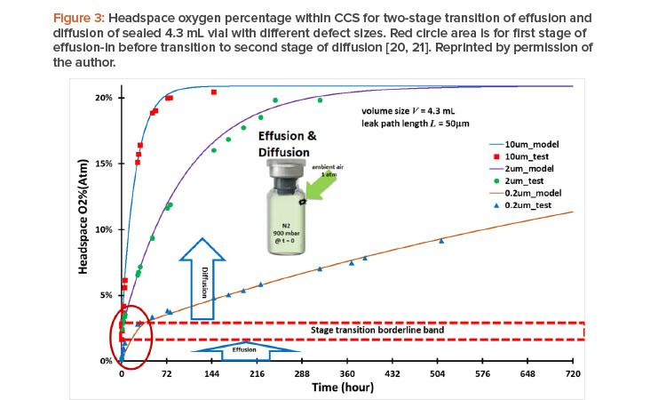
Container closure system performance must be qualified for acceptable container closure integrity. Container closure integrity is associated with the size of the leak path of the container closure system. Figure 3 shows container closure integrity modeling case study data of headspace of oxygen ingress through different leakage defect sizes20 together with testing results.21 For this case study, all three vials were subjected to the same conditions —the same 4.7 mL vial volume with 50 mm defect path length but different leak path diameters (d = 10 mm, 2 mm, and 0.2 mm, respectively); lyophilized, filled with 100% nitrogen gas, and evacuated to end pressure at 900 mbar—before being stoppered and capped tightly at time zero. The ambient air pressure is at 1 atm (1,000 mbar). This is a case of effusion-in. The term “effusion” is generally used in the parenteral packaging industry for gas leakage transmission, including concurrent diffusion and mass/volumetric flow into or from the vial. The diffusion is driven by the gas concentration differential. The mass/volumetric flow is driven by the total pressure differential, and oxygen ingress into a vial through a leak path can be calculated. Figure 3 shows the modeling results20 and testing results21 of headspace oxygen percentage over time.
Two stages of effusion and diffusion, respectively, through a seamless transition in real time are shown in Figure 3:
- The first stage started with effusion-in and concurrently included both diffusion and mass/volumetric flow into the vials at time zero, with a total pres-sure differential of 100 mbar (1,000 mbar – 900 mbar = 100 mbar). This effusion-in stage ended once the total pressure differential fully dissipated and reached pressure equilibrium with no more mass/volumetric flow.
- However, the inside of the vial is still oxygen deficient at the end of the first effusion-in stage because of the prior presence of nitrogen. The second stage immediately and seamlessly started as oxygen diffusion continued from the first stage into the vial without mass/volumetric flow in the second stage, eventually reaching a headspace oxygen pressure of 20.9% atm and equilibrium with the oxygen percentage in ambient pressure.
The modeling data accurately capture the stage transition points from the first effusion-in stage to the second diffusion stage, as highlighted by the red circle area in Figure 3. The oxygen percentage at the stage transition point differed from one leak path diameter to another. The timing of the total pressure equilibrium and its corresponding oxygen percentage depends on the defect diameter: about 8.9 seconds and 2.29% oxygen (atm) for a 10 mm diameter; about 8.3 minutes and 2.37% oxygen (atm) for a 2 mm diameter; and about 43.82 hours and 3.07% oxygen (atm) for a 0.2 mm diameter; all corresponding to the stage transition borderline band in Figure 3.
Clearly, when the leak diameter is bigger, the time to total pressure equilibrium is shorter, and the oxygen percentage (atm) is slightly lower when the end of the first stage is reached, owing to the predominance of quick mass/volumetric flow through the leak path, with little oxygen diffusion taking place simultaneously in the first stage. For a smaller leak diameter, it takes longer to reach the total pressure equilibrium, with a slightly greater oxygen percentage (atm) at the end of the first stage because more oxygen diffusion occurs simultaneously in that stage. It is clear that the size of a leak path has an impact on container closure integrity. Modeling calculations can help provide quick screening evaluations in many cases when the testing method is either too limited or too costly.20
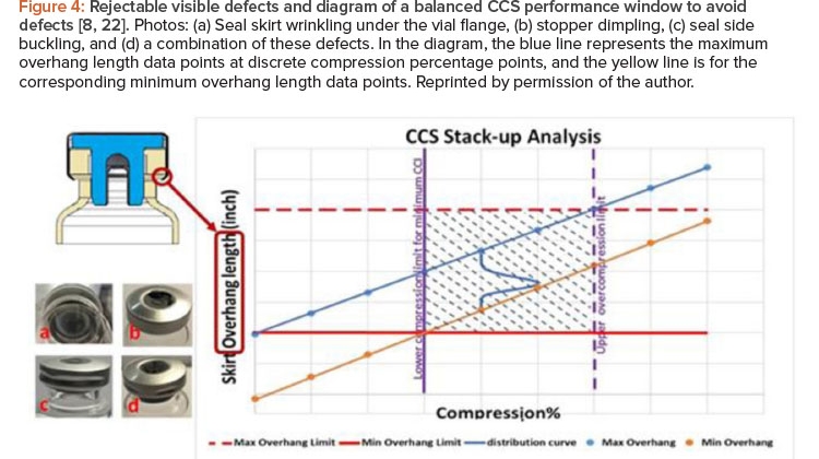
![Figure 4: Rejectable visible defects and diagram of a balanced CCS performance window to avoid defects [8, 22].](/sites/default/files/2021-09/0921_PE_SO_TechZeng_04.jpg)
Several Container closure integrity testing methods are commonly used in the pharmaceutical industry to quantify the magnitude of container closure system leakage for regulatory compliance (recalling that no container closure system should permit leakage beyond the MALL). Container closure integrity testing methods can be deterministic or probabilistic: deterministic methods include helium leak testing, high voltage leak detection, laser headspace analysis, mass extraction, and pressure and vacuum decay methods; probabilistic methods include bubble leak and blue dye tests. With deterministic methods, the measurement of leak detection is based on physicochemical technologies that are readily controlled and monitored, yielding objective quantitative data. For this reason, the pharmaceutical industry has increased efforts to introduce and develop deterministic leak test methods for container closure integrity testing.
However, any type of testing technique may have limitations based on many factors, including:
- A specific testing setup under highly specific testing conditions
- Destructive methods that do not occur under real-world conditions
- The inability with destructive methods to iterate testing on the same sample to identify trends
- Lengthy testing times for trending results from slow leakage
- Issues with representative sampling
- The resulting inability to reproduce and predict results for various real-world applications
Many aspects must be considered in a holistic container closure integrity testing approach. There is no universally accepted container closure integrity testing method, and each testing method and principle has merits and shortcomings. It is important to understand the science behind why a container closure integrity testing method is chosen to ensure integrity, especially because there is a direct correlation between container closure integrity and patient safety. The container closure system package must be validated to ensure container closure integrity can be maintained throughout the entire drug product shelf life.
Optimal Container Closure System Performance
The quality of the final vial container closure system package is determined by both the container closure system components (vial, elastomer stopper, and aluminum seal) and the capping process. Empirical experience indicates that unexpected failure, manifesting as container closure integrity failure, visual defects, or incomplete sealing, can occur over time. Therefore, choosing the appropriate elastomer stopper, vial, and aluminum seal, together with a capping and sealing process optimized around those components, is essential to ensuring reliable container closure integrity and optimal container closure system performance.
Engineering drawings can specify a range of dimensions for container closure system components. Due to variations in manufacturing, each component of a container closure system is a statistical variable. It is important to understand the statistical variations of the components, especially when limited information is available on compatibility or when multiple suppliers are utilized. Because of these variations, it is difficult to assess the likelihood of successful assembly, capping, and sealing for a given vial container closure system when setting up a pharmaceutical capping process. In general, a capping process must be set up with proper stopper compression to ensure the residual seal force is sufficient at both time zero and throughout the entire sealed drug product shelf life to maintain container closure integrity. However, excessive stopper compression may cause visual defects or crash container closure system, which adversely affect the acceptance of a vial assembly.
CCI must be stable under the multitude of potential circumstances that a vial product might encounter over its shelf life.
Figure 4 shows example photos of rejectable visual defects caused by excessive stopper compression during the capping process that resulted in visual inspection failure on the manufacturing floor.8, 22 Other defects caused by excessive stopper compression are possible. For example, excessive force can also crack glass vials and cause container closure integrity failure.
In light of the multiple challenges associated with vial container closure system performance, it is imperative to strike a balance when satisfying all container closure system performance needs. Container closure system dimensional variations may lead to capping failure, which results in container closure system visual defects, container closure integrity failure, or the potentially costly rejection of an entire container closure system production batch. Container closure system stack-up optimization is designed to clearly define and locate a balanced window to satisfy both residual seal force and container closure integrity while also providing an acceptable visual appearance. Figure 4 displays a balanced container closure system performance window,8, 22 where the horizontal axis represents the stop-per flange compression percentage and the vertical axis represents the seal skirt overhang length (defined by subtracting the summation of the stopper flange thickness and the vial flange thickness from the overall seal skirt length).
After completion of the capping process, the vial container closure system stack-up dimension characteristics (in the rectangular shadowed area in the chart on Figure 4) of the vial assembly are described as follows:
- Seal skirt overhang length will depend on the original stopper flange thickness and its compression percentage, but it must be larger than the minimum overhang limit (horizontal red line in Figure 4) if the container closure system components are to be properly assembled.
- To avoid the seal skirt wrinkling issue under the vial flange, seal skirt overhang length should be less than maximum overhang limit (horizontal dashed red line in Figure 4).
- Stopper flange compression percentage must surpass the lower compression limit to ensure sufficient residual seal force and to not exceed the MALL throughout the entire sealed drug shelf life for acceptable minimum container closure integrity.
- Stopper flange compression percentage should not be excessive or beyond the upper compression limit to avoid visual defects such as, but not limited to, seal skirt wrinkling under the vial flange, stopper dimpling, seal side buckling, or a combination of these defects.
The stopper flange thickness, vial flange thickness, and seal skirt length are statistically variable data typically available from the container closure system component manufacturers as a part of their routine quality assurance procedure. These container closure system component dimension variables can be statistical input into calculations to evaluate the container closure system’s end performance and its quantitative failure risk in terms of its sealing performance and visual acceptance.
The statistical stack-up distribution curve can be calculated to not only identify the condition that suits a process but to also quantify the data-driven risk assessment of being outside the performance window (shadow area in Figure 4) over a range of conditions. As a result of the container closure system stack-up, the seal skirt overhang length also becomes a statistical variable, in addition to its dependence on the actual stopper flange compression percentage. The statistical distribution of the overhang length is schematically represented as a blue curve in the Figure 4 chart, and it will move along the track between the blue line and the yellow line depending on the actual compression percentage. The goal is to ensure that the blue distribution curve of overhang length is positioned within the rectangular shadowed area on the chart in Figure 4, which is the optimal performance window. This will lead to the satisfactory container closure system performance described earlier when correlated with container closure integrity data. For data-driven risk management, the quantitative risk of being outside of the rectangular container closure system performance window in Figure 4 can be calculated based on the actual statistical distribution of stopper, vial, and seal.
This mapping capability is powerful for pharmaceutical engineering applications because the cost of manufacturing defects can be high, ranging from the rejection of entire lots to product recalls. Using this real-data approach, the most probable assembly for each container closure system can be identified, as well as the range of seal skirt overhang lengths encompassing any percentage of assemblies in the performance window at any stopper compression.8, 22 In general, this comprehensive approach of stack-up calculations can assist in selecting and evaluating the compatible container closure system components and appropriate stopper compression, as well as in troubleshooting container closure system performance concerns and ensuring the process is operating within the optimal container closure system performance win-dow. This optimal performance window for container closure system compatibility can be calculated, simulated, predicted, tested, and assessed for critical data-driven risk management, provided that sufficient container closure system component data are available from the quality assurance database across container closure system component manufacturers for life-cycle management.
Conclusion
A systematic pharmaceutical engineering approach for ensuring acceptable, compliant performance of vial container closure systems must include choosing qualified container closure system components, a proper capping process setup, and applicable testing methods. Container closure system performance includes both container closure integrity and visual inspection acceptance. Characteristics of the elastomer stoppers play a critical role in delivering vial container closure system performance through well-balanced material properties, overall container closure system compatibility, and dimensional compressibility to accommodate the capping process window. The sealing performance of the elastomer stopper is inherently time- and temperature-dependent during the container closure system shelf life, and cold temperatures may adversely impact container closure integrity. Further considerations, which are beyond the scope of this article, include other environmental conditions (e.g., moisture, light exposure, handling, vibration, shock, impact). Using a systematic data-driven approach will aid informed decision-making when choosing compatible container closure system components as well as ensuring they are assembled and tested in an appropriate manner to minimize the potential risk for patient safety. Together, these steps will ultimately deliver a container closure system that ensures a consistently high level of performance.
About the Author

Acknowledgements
The author thanks Allison Radwick for coordinating the internal review process of the manuscript. The author also thanks all reviewers for their many constructive suggestions during the peer review process.


