Technical
May / June 2021

Analyzing System Performance through Process Instrumentation Data

Albert Dyrness
Andrew A. Lamore
Ravi Shankar
Figure 1: Simplified CIP skid system.

What if the reliability of a system could be improved by accessing the standard data provided with modern process instrumentation? These data, accessed from existing instrumentation, can be used to analyze the fitness of processes, equipment, and instruments; better understand processes; support discrepancy investigations; and provide a data-driven basis for the timing of maintenance and calibration. Most instruments in a modern biopharmaceutical manufacturing facility can provide this type of information; this article covers a few particularly illustrative examples in detail.

Biopharmaceutical manufacturers rely on process instrumentation to measure and record key and critical process parameters, which are often the basis for regulatory licensure. Risk control strategies include the use and interpretation of these instrumentation data to ensure compliance. For GMP systems, any data management and usage must comply with GAMP® 5 guidelines,1 ensuring data reliability and integrity.

Process failure detection in system design is critical to reducing the overall risk to the patient and to improve process reliability. The design of process failure detection can be fortified through redundancy, which is typically accomplished through the addition of redundant instrumentation.2 However, it is also possible to create redundancy by correlating existing data from process instruments that are already part of a unit operation.

Most unit operations include multiple instruments to monitor and control critical process parameters. Many individual measurements within a unit operation can be correlated to provide redundancy without additional instrumentation. The rapid development of instrumentation in recent years has resulted in standard instrumentation that has the inherent capability to not only measure the primary process parameter but also produce additional process parameters and other valuable information available to the user.

Correlating Process Variables in Unit Operations

The idea of correlating two or more independent process variables to establish the process conditions is not new. Dalton’s law states that the sum of the partial pressures is equal to the total pressure. In other words, when noncondensable gases are present in saturated steam, the total pressure indicated will be higher than the corresponding saturated steam pressure.

This is the basis for a typical “air-in-chamber” alarm on standard automated steam sterilizers; the alarm signals when a pressure measurement does not equal the saturated steam pressure at the corresponding temperature. This alarm is critical in a sterilization unit operation, as the presence of non-condensable gases can significantly reduce the efficacy of moist heat sterilization. The following are examples of unit operations used in bioprocessing where correlations among independent process parameters can be used to better understand the state of the process.

Clean-in-Place Unit Operation

One critical parameter during a clean-in-place (CIP) process is flow rate. In addition to a flow meter, most CIP systems include a pump discharge pressure transmitter, as shown in Figure 1.

For a centrifugal pump with a known pump speed, the pump curve and affinity laws can be used to draw a direct correlation among flow rate, pressure, and pump speed (the latter is often inferred from the output of a frequency-controlled variable speed drive). Trending and interpreting all three parameters can provide valuable information regarding any changes to the system due to wear, damage, or instrument degradation.

Another critical parameter for a clean-in-place unit operation is chemical concentration. The concentration of common cleaning chemicals, such as sodium hydroxide and phosphoric acid, can be determined by their conductivity at a given temperature, which is often inferred via a reading from a temperature-compensated conductivity instrument. A modern conductivity sensor can accurately measure both the chemical wash and water for injection (WFI) rinse process steps—even though they are orders of magnitude apart—by using a single probe 4-pole conductivity sensor.

The actual chemical concentration is determined by the combination of circuit volume, clean-in-place tank level, and actual volume of chemical quantity dosed. Chemical dosing control systems independently deliver a specific quantity of concentrated cleaning chemicals to the clean-in-place system in one of two ways: by calculating the “pump-on” time or by calculating the number of pulses given to the pump.

Both the steady-state conductivity and the dosing quantity can be correlated. The variance between these established correlations is an indication of a change to the system performance, or a change in the repeatability or accuracy of the associated instrumentation.

Chromatographic Unit Operation

Creating redundancy by developing correlations between independent parameters is also applicable to chromatographic unit operations. Precolumn conductivity is used in chromatography to monitor chemical concentration during inline dilution. An inline flow cell assembly that integrates pH, conductivity, and ultraviolet measurements with a single transmitter can be used to reduce holdup volume. In addition to the conductivity meter, chromatography systems are generally equipped with flow meters (one for WFI and one for the concentrated buffer), as shown in Figure 2.

Even though the pump speed ratio may be controlled by the resulting conductivity measurement, a change in the ratio from the established value will indicate whether the supplied buffer concentration has changed or whether the instrumentation or pump performance is starting to degrade.

Sometimes redundancy exists, but only for specific points in a unit operation. During a typical chromatographic process, there will be points where the conductivity of the supplied buffer does not change as it flows through the column. These points present an ideal opportunity to record and compare the pre-and postcolumn conductivity as a health check on the conductivity probes.

Sometimes the data exist but a calculation is required to evaluate the effectiveness of a unit operation. It is standard practice to perform an asymmetry test to assess the column integrity after packing and prior to use. Introducing a narrow pulse of a known solution into a column (see Figure 3a) will result in an uneven spread due to axial dispersion as the solution exits the column. The uneven spread is characterized by the asymmetry, As = a/b, as shown Figure 3c.

fig 1

  • 1International Society for Pharmaceutical Engineering. GAMP® 5 Guide: Compliant GxP Computerized Systems. North Bethesda, MD: International Society for Pharmaceutical Engineering, 2008.
  • 2Butler, J., and C. Smalley. “An Introduction to Predictive Maintenance.” Pharmaceutical Engineering 37, no. 3 (2017): 63–65.
Figure 1: Simplified CIP skid system.

Figure 2: Simplified chromatography skid system.

Although the typical chromatographic recipe does not include pulses, it does include step changes in buffers that run through the column, and these buffers often have different conductivities. The sharp step, as seen by the change in buffer conductivity (Figure 3b), will leave the column in an S-shaped curve—sometimes referred to as a frontal curve3 ]—due to the same axial dispersion observed in the asymmetry test shown in Figure 3d. The area under the curve of the dispersed pulse also results in the S-curve.3 So, by differentiating the S-curve (Figure 3c), a dispersed pulse can be calculated, from which the asymmetry can be estimated, as shown in Figure 3b. This calculation allows the column integrity to be confirmed during and between batches, providing a real-time assessment of the column integrity. The data are readily available from those already typically used in a standard low-pressure liquid-chromatographic unit operation.


Figure 3: Impulse trace versus step change trace in evaluating asymmetry.

Figure 4: Simplified HTST skid system.

High-Temperature-Short-Time Unit Operation

A critical parameter during a high-temperature-short-time (HTST), or pasteurization, unit operation is the temperature in the retention tube. Most HTST systems monitor both inlet temperature and outlet temperature of the retention tube (see Figure 4). Except for external heat loss, these two temperatures should be identical, as retention tubes are insulated sufficiently to maintain a nearly constant temperature. During steady-state operation, the difference between the inlet and outlet temperature, if any, should be the same over time, and any change to this difference could be an indication of instrument degradation. In these situations, if one instrument is found to be outside the established calibration tolerance, the second instrument is then relied upon to access any resulting discrepancies. Through continuous monitoring and comparison, predictions can be made about the timing of the next calibration of the temperature instrument(s). This approach puts the calibration program on a data-driven schedule instead of requiring a rigid, fixed schedule, which could lead to premature or wholly unnecessary calibration.

Another good example for the HTST unit operation is an open-loop control strategy versus a closed-loop one. Typically, the heating and cooling of an HTST system are controlled by modulating temperature control valves. During steady-state operation (constant flow conditions), the temperature control valve stem position should remain within a narrow range, unless the feed product temperature varies significantly. Even so, the energy required to raise or lower product temperature is directly related to the position of the temperature control valve. Monitoring the temperature control valve position as a closed-loop control circuit can provide an early indication of changes to the heat exchanger performance or potential fouling. Over time, if the control valve positions are then historicized, these data can provide an indication of the system performance—even when all the critical process parameters are being met.

Smart Instruments

In this article, the term “smart instruments” does not refer to the internet of things. Rather, it is used to describe instruments that have a level of sophistication that allows for detecting process conditions well beyond the process parameter of interest. One of the simplest types of instrument in the smart instrument class is a conductivity meter with integrated direct temperature compensation, as referenced in the previous CIP unit operation example. This instrument measures an additional process parameter (temperature) as well as the parameter of interest (conductivity). Although operators do not typically rely upon the conductivity instrument as a replacement for a resistive temperature device (RTD), the temperature measured by the conductivity instrument can provide a redundant measurement of process fluid temperature for a specific unit operation.

The following are other examples of modern process instrumentation that have a similar level of sophistication and can provide additional data in a similar way.

Smart Liquid Flow Meter

Today’s modern smart liquid flow meters provide much more than the process parameter of interest (flow rate), including instantaneous mass and volumetric flow rates, totalized mass flow, density (specific gravity), viscosity, turbidity, flow turbulence, temperature, amplitude and speed of raw signal, percentage of gas entrainment, gas bubble size, concentration of a known liquid, deviation from original calibration, and out-of-specification flags. Ac-cessing these additional parameters only requires establishing the input/output (I/O) communication from the instrument and the control system and then determining whether it is repeating (cyclic) or on-demand/on-event (acyclic).

One example of a smart liquid flow meter application concerns the timing between bowl discharge operations of a disk stack centrifuge, which depends on the time it takes to load the bowl. A strong indication of bowl loading is supernatant turbidity. Using a smart liquid flow meter, the turbidity can be monitored and used to establish the timing of bowl discharges.

The smart liquid flow meter can also be used to instantaneously differentiate between two fluids when monitoring the retentate—or permeate—of an ultrafiltration process, as illustrated in Figure 5. Deviations in the flow instrument’s raw signal amplitude and speed, in addition to the expected volumetric flow rate, can help determine whether the process fluid contains protein in suspension or only buffer. These data can then be interpreted to identify the condition as abnormal (e.g., a filter membrane failure when there is protein present in the permeate outlet) or normal.


Figure 5: Contextual data for an ultrafiltration process.

Sensor Health

Many of today’s smart instruments have the ability to self-diagnose and perform instrument self-checks. For example, pressure transmitters can self-diagnose electrical loop integrity and process connection integrity.4 Smart instruments also often include internal diagnostics. The process instrument parameter verification is a method of “confirming” that a predetermined condition is fulfilled and the instrument meets the intended output based on the manufacturer’s specifications. This differs from a standard calibration check in which the instrument output is verified against a reference standard.

Smart liquid flow instruments also provide other diagnostic information as standard: the tag/P&ID number; hours of operation; manufacturing date and firmware version; internal diagnostics; buildup on, coating of, or corrosion of tubes; maintenance due date; calibration state; name of person who performed the last calibration; date of last calibration; all device I/O registers at that time (a snapshot in time); sensor integrity; and regulatory reports.

For a smart liquid flow meter, onboard verification can provide reliable data to prove it is operating according to its specifications. When a device is equipped with built-in algorithms, all test sections (sensor, front end, reference, and I/O loop) are monitored continuously and are part of the standard device diagnostics. If verification is initiated, the current status of all diagnostics parameters can be read and stored for periodic review.

In the case of a Coriolis mass flow meter, the mechanical stiffness—or rigidity—of Coriolis flow tubes is directly related to the meter’s flow calibration factor. The verification can identify changes, damage, or degradation in the measurement performance of the instrument. This could be especially important in verifying the flow meter’s integrity after process disturbances or upset conditions.

Smart Proximity Sensors

Proximity sensors, or limit switches, have historically been characterized as the antithesis of a “smart” instrument. Proximity sensors are ubiquitous in systems that require valve position feedback, and, historically, they have been simple mechanical devices that rely on an extension of the valve stem to close a contact. However, in recent years, these devices have undergone revolutionary technological developments that have broadly expanded their capabilities while maintaining simplicity in all other aspects.

Control valve stem travel can be characterized as a function of actuator pressure,5 and the sensing of the valve stem movement is no longer limited to typical noncontact proximity sensor technologies such as those using inductive, capacitive, photoelectric, or ultrasonic principles. With the inclusion of Hall effect and variable differential transformer technology applied to both linear and rotary modes of operation—commonly known as linear variable differential transformers and rotary variable differential transformers, respectively—these once-simple devices are now capable of providing over 30 different parameters, which range from an autoconfiguration of the limit switch tolerances to measuring the current actual valve stem position to a fraction of a millimeter of measurement resolution. Evaluation of these data by a supervisory control and data acquisition or distributed control system—either cyclically or acyclically—can be extremely useful to the system user in determining preventive maintenance requirements and process changes.

Self-Diagnosing and Intelligent RTDs

The most common temperature sensor used in bioprocess applications is the three-wire, platinum-100-ohm RTD instrument, which can also have an integral digital or analog transmitter. These sensors are regularly calibrated to maintain measurement accuracy and process reliability for any unit operation.

Temperature redundancy is sometimes achieved through the use of dual thin-film element RTD instruments. For standard temperature instruments with transmitters, the instrument itself can detect failures and changes from the initial calibrations. This is typically achieved by comparing signals from the two elements, and should the first element fall out of tolerance, the onboard diagnostics are programmed to switch over to the second RTD element as the primary process variable.

In addition, some modern RTD instruments with integral transmitters can perform a live “self-calibration” check. This is accomplished using a physical fixed point known as the Curie point, or Curie temperature, which is the temperature at which the ferromagnetic properties of a material change abruptly. This change in properties can be detected electronically. The sensor uses this value as the reference against which the RTD instrument measurement is compared.

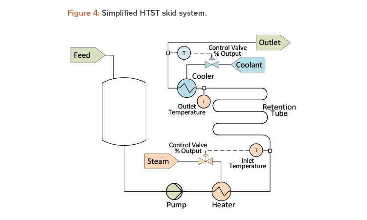
Given that temperature is one of the top three process control parameters used worldwide (along with flow and pressure), it is certainly one parameter that could benefit from the use of these advanced diagnostics provided by “smart instruments.” Examples of ideal applications of smart RTDs with self-calibration check capabilities include steam sterilization of equipment or autoclaves, HTST operations (viral inactivation or pasteurization), lyophilization operations where shelf temperature is a critical parameter, depyrogenation/dry heat ovens, cleaning operations, and steam-in-place operations.

Conclusion

A vast amount of data is available through correlating existing instruments2 or by accessing the internal data of modern smart instruments, and these data can be used to improve process knowledge, support discrepancy investigations, increase production, minimize risk in critical processes, schedule maintenance cycles, and assess the entire system or simply process instrumentation performance over time.

The practice of using the information available from an instrument for purposes other than its primary parameter of interest has been suggested by others and is not unique to biopharmaceutical manufacturing, as evidenced by the cited references. The data can be accessed by existing control systems and analyzed via asset management systems or processed via data historians and other similar data acquisition tools. Although it takes a deliberate effort to profile these processes, historicize data, and perform comparative calculations, there are clear value propositions to any biopharmaceutical manufacturer, such as real-time sensor health checks and process performance measurement, batch release through discrepancy resolution, predicting equipment or instrument degradation, data-driven maintenance and scheduled downtime, and processes running at maximum availability and stability.

Accessing “hidden” data inherently available in modern process instrumentation helps a facility not only achieve these goals but also improve both overall process knowledge and understanding of unit operations.