Lyophilizer Instrumentation Calibration: Principles & Practices

Historically, the pharmaceutical industry’s focus has been on the lyophilization process and equipment, but discussion about calibration of process monitoring and control instrumentation has been quite limited. Recently, focused attention has been given to control and monitoring instrumentation for lyophilization.
In 2017, Nail and colleagues published an overview of various process monitoring methods and devices that addresses temperature and pressure measurement.1 Still, the industry lacks consensus about best practices. A greater understanding of the science and technology of lyophilization drives improvements in calibration, which leads to better process control and increased confidence in achieving product quality.
Calibration Requirements
Calibration requirements for the lyophilization process are unique. For example, the process includes a temperature range from extreme cold during freezing to relatively high temperatures during sterilization, as well as multiple pressure ranges. This relatively wide range of conditions poses specific needs that require careful consideration in addressing calibration.
Furthermore, the critical process parameters (CPPs) that directly affect the finished product’s critical quality attributes (CQAs) warrant different attention than key process parameters (KPPs), which reflect process conditions and equipment performance. Temperature, pressure control, and time are well recognized as the principal critical process parameters for lyophilization.2
Eachcritical process parameters or key process parameter requires specific levels of accuracy, precision, and resolution. A thorough knowledge of the instrumentation and an understanding of the process form the foundation for a well-developed calibration program. This is essential to providing a high level of confidence in parameter measurement and process control.
A well-developed calibration program needs to encompass complete and comprehensive procedures, an effective management system, and capabilities to conduct calibration that spans the entire operating range of the equipment with an adequate resolution.3
Proper calibration of an instrument provides confidence that the reported values accurately reflect the process condition for each measure made. During batch manufacture, well-calibrated instruments are critical to achieve and verify reproducibility of the process for each batch. Adequate accuracy and precision in measurements ultimately establish confidence that the desired level of product quality is continually achieved.
Lyophilization Overview
Lyophilization is a drying process for preservation of sensitive pharmaceutical products. This process is conducted over a range of subambient to elevated temperatures and a range of subatmospheric pressures. The three principal parts of the process—freezing, primary drying, and secondary drying—are conducted at different combinations of these temperatures and pressures. Freezing occurs at temperatures as low as –55°C and at or near 1 atmosphere. Primary drying is conducted at both low temperatures and low pressures. Secondary drying is completed at ambient or warmer temperatures and, by convention, low pressures. These varied conditions present unusual challenges in ensuring proper calibration.
In principle, the lyophilization process is driven by the environmental conditions created by the lyophilization equipment. Through the use of a circulating heat-transfer fluid, the product shelves function as heat exchangers, where transfer of heat from the product during freezing and to the product during drying is accomplished by controlling the shelf temperature. The shelf temperature is measured and monitored using a resistance temperature detector (resistance temperature detector) in a thermowell immersed in the heat-transfer fluid supplied to the shelves.
The required pressures during the drying phases are achieved by evacuating the atmosphere in the lyophilizer to a relatively low pressure, and controlling the pressure to a specific level by introducing an inert gas, such as sterile filtered nitrogen. The low pressure is measured and monitored using an electronic pressure sensor with the capability to detect pressures at a fraction of 1 atmosphere (760 mm Hg at sea level) and resolving such pressures to at least 1/760,000 of 1 atmosphere (0.001 mm Hg). This electronic pressure sensor is located on the product chamber and condenser vessel. These conditions of shelf (inlet) temperature and chamber pressure are critical process parameters (i.e., process parameters that directly affect finished product quality). Critical process parameters and key process parameters for lyophilization are presented in Table 1.4
Table 2 lists the desirable range and resolution for temperature and pressure measurements based on the parameters used for lyophilization. For lyophilizers used in preparation of sterile products and sterilized using saturated steam, the temperature range would increase to 130°C.
Process conditions of temperature are reported in engineering units of degrees Celsius (°C). Typically monitored lyophilizer components are the shelf inlet temperature as acritical process parameter, and the shelf outlet and condenser temperatures as key process parameters. Temperatures of other parts of the system (such as subcooled refrigerant into the expansion valve, heat-transfer fluid into and out of the heater unit and each refrigeration unit heat exchanger, and cooling water to and from refrigeration units) are also monitored, primarily to assess performance and for maintenance purposes.
There are generally two scales used for reporting pressure: small fractions of 1 atmosphere, which are reported in hundreds of units, and large fractions of 1 atmosphere, which are reported in tenths. During freezing, and then again during stoppering of vials at the end of secondary drying, chamber pressure may be monitored and controlled to units of pounds per square inch (PSIA) or bars in tenths of 1 atmosphere. During primary and secondary drying, pressures are often measured in tens to hundreds of microns of mercury (µm Hg) or microbars (µbar). The pressure range spans from a few microns or a few microbars to up to 10,000 µm Hg (13,000 µbar).
References and Standards
Standards should be guided by an international or national primary standard from an authority such as the International Bureau of Weights and Measures (BIPM) or the National Institute of Science and Technology (NIST) in the US. These primary standards are used to determine reference (secondary) stand-ards. Calibration labs then use these secondary standards to calibrate the working standards. Working standards are used by individuals to calibrate instruments for controlling and monitoring equipment and processes.
| Parameter Type |
Definition | Examples |
|---|---|---|
| Critical process parameter (CPP) |
A condition that may directly affect finished product quality |
• Shelf (inlet) temperature • Chamber pressure • Time |
| Key process parameter (KPP) |
A condition that may affect a CPP but does not directly affect finished product quality |
• Condenser: temperature sensor attached directly on the condenser surface or at inlet and outlet • Shelf outlet temperature • Heat-transfer fluid temperature (refrigeration unit heat exchangers, outlet from heater) • Condenser pressure • Vacuum pump(s) inlet pressure |
| Engineering Unit |
Range | Resolution |
|---|---|---|
| °C | –80.0 to 50.0 | 0.1 |
| μm Hg | 1 to 10,000 | 0.1 |
| μbar | 1 to 10,000 | 0.1 |
| PSIA | 0.0 to 35.0 | 0.1 |
| mm Hg | 1 to 760 | 1 |
| Bar | 0.00 to 1.00 | 0.01 |
Guardbanding
In conjunction with establishing an acceptable tolerance, an approach called “guardbanding” may be used when clearly defined within the calibration procedure. Guardbanding adjusts tolerance for an instrument to be within a narrower range relative to the allowable instrument tolerance.5 Guard-banding can mitigate the risk of an out of tolerance (OOT) measurement due to drift in the measurement accuracy or uncertainty.
For example, suppose a unit under test (UUT) has an upper-temperature limit or tolerance of 0.5°C and the accuracy of the working standard reference being used to measure the temperature is ±0.1°C. When the unit under test is at its limit of 0.5°C, the actual value may be anywhere from 0.4°C to 0.6°C, due to the accuracy of the working standard reference. This means that there is a reasonable possibility that 50% of the time when the unit under test is at its tolerance limit of 0.5°C, the unit under test may actually be beyond its limit. Depending on the process, exceeding 0.5°C may pose a serious risk. In this case, applying the guardbanding method to set an actual tolerance limit of 0.4°C could reduce the risk that the reference system would result in a false acceptance.
Guardbanding may also be used to prevent drift of an instrument’s calibration from causing a future out of tolerance result. For example, suppose a unit under test has a calibration tolerance of ±1°C. If the instrument were found during a routine calibration check to be near or at that tolerance limit, it would be appropriate to make a calibration adjustment to bring that unit closer to the temperature indicated by the working reference. Technically, the unit under test would be within tolerance and no calibration adjustment would be necessary. However, if the unit’s calibration were to drift another 0.1°C before the next routine calibration, that would cause an out of tolerance result. Had the unit been adjusted to within 0.5°C of the reference temperature during the previous calibration, the unit would still be within the acceptable calibration tolerance even after the 0.1°C drift.
Guardbanding can quickly become complicated when a rigorous approach of the principle is applied to a calibration program, particularly when uncertainty calculations are considered. For field-level calibrations, a simple guardbanding practice—such as specifying an adjustment when the value is equal to half a unit’s calibration tolerance—may be sufficient. For example, it may be desirable to adjust an instrument when the difference from the working reference instrument approaches 0.3°C. This accommodates any instrument or sensor drift over the interval between calibration checks. Or it may be desirable to select a range at which an adjustment is directed within the procedure to avoid approaching a tolerance limit or even a guardband. Such a pragmatic approach is based on establishing a desired variation from the reference value for making an adjustment, considering the criticality of the temperature or pressure relative to the critical process parameter.
A more rigorous approach is to add the allowable uncertainty for each instrument in the chain of reference standards from the primary standard to the working standard used for calibration. In essence, it is the sum of the errors for each factor that may contribute to a level of uncertainty for the calibration.
| Device | Uncertainty |
|---|---|
| Working standard | 0.025°C |
| Dry block uniformity | 0.05°C |
| Sum of uncertainties | 0.075°C |
| TUR | 4 |
| Guardband around target | 0.3°C |
Table 3 lists uncertainty levels as sources of error for a calibration. Using these values as an illustration and assuming a reasonable test uncertainty ratio (TUR) based on the sum of the tolerances would provide a total measurement uncertainty. This approach would yield an uncertainty level of 5%, or a confidence level of 95%.
Many resources6, 7, 8, 9 explain the concepts and principles of uncertainty and guardbanding, with official industry requirements outlined in ANSI/NCSL Z540.3-2006 (R2013): Requirements for Calibration of Measuring and Test Equipment.10
Calibration Program Requirements
A well-developed calibration program has three essential aspects: methodology, administration, and the calibration itself.
Methodology
Proper calibration methods inspire confidence that an instrument will render accurate measurements. Establishing a proper and effective methodology requires a thorough understanding of the process in conjunction with basic knowledge of the instrumentation. It is also important to recognize that the entire process operating range is crucial for assurance of the measured parameters.
Calibration frequencies and tolerances should be well defined and reflect the criticality of measurements for different parameters within the lyophilization process. When describing an allowable tolerance, if the desired confidence is to be within one-half of 1°C, the tolerance may be stated as less than ±0.5°C. If a tolerance up to one-half of 1°C is acceptable, the tolerance may be stated as equal to or less than ±0.5°C. For such resolution, the results comparing the reported temperature relative to the working standard should be reported to one-tenth of a degree (0.1°C).
The desired tolerances should be tailored to the process rather than the instrument’s capable range. Some temperature measurement and control instrumentation may have an operating range for measuring from –100°C to 400°C (a span of 500°C), while the process range being monitored may be –80°C to 50°C (a span of 130°C). There is potential to experience reduced accuracy and precision with calibrating to the wider instrument span of 500°C rather than to the narrower process span of 130°C. In general, the smaller the range evaluated for calibration is, the greater the accuracy and precision will be. If an instrument cannot be calibrated to the level needed for process control, the instrument is not appropriate for the task.
Through trending, it is possible to provide some flexibility in the requirements for calibration frequency and tolerances and adjust them based on performance. For example, suppose critical process parameters and key process parameters for a process and equipment are monitored by a high-quality stand-alone process recorder for electronic data storage, with the ability to present process data in a trend or alphanumerically. The calibration procedure for such an instrument allows for calibrating a complete range of input channels, all at the same time, to the same reference, and to the same tolerance. It is expected that the calibration of an instrument monitoring shelf inlet temperature (a critical process parameter) will be verified every six months and be within a 0.5°C tolerance. The same instrument may monitor and record the shelf outlet and condenser temperatures (key process parameters), and the subcooled refrigerant temperature (a variable of interest for maintenance). Although the calibration expectation for an instrument monitoring these key process parameters is an annual verification and a tolerance of equal to or less than ±1°C, the extra effort to check each sensor semiannually when the shelf inlet is checked and to use the same tolerance for all calibrations is justified by the increased confidence in the monitoring data provided.
Administration
Administrative oversight ensures a proper calibration program is being implemented, and performance of calibration is timely and consistent. Detailed and standardized calibration procedures, a tracking system for all required instrument calibrations, and a thorough review process are vital.
It also may be helpful to implement trending of repeatability and any drift to evaluate instrument suitability and reliability. This trending can demonstrate robustness and may lead to shortening or extending a calibration interval. Considering the ultimate goal of a high level of process control, these components should be tailored to work together in an effective and efficient manner.
The standard operating procedures (SOP) need to be clear, concise, and comprehensive such that any person reasonably trained in instrumentation and electronics would be able to successfully complete a calibration activity. The procedures should be specific to the instrumentation requiring calibration, as well as the criticality of the measurements. The standard operating procedure and accompanying data sheets are most useful when important information is included in each section, as outlined in Table 4.
It is imperative to include the rationale for the frequency and allowable tolerance in the standard operating procedure. A simple statement such as “This instrument measures and controls a critical process parameter of shelf temperature and is to be calibrated every six months, with an allowable tolerance of equal to or less than ±0.5°C” clearly conveys the importance of the instrument and the relative impact of proper calibration. If a sensor is monitoring a key process parameter, less-frequent calibration and a wider tolerance may be acceptable.
An effective and efficient management system is essential to ensure adequate and timely calibration activities. A resource planning tool is an easy way to quickly assess the status of any instrumentation and equipment.
The best management system will depend on the company’s specific organizational structure. Basic elements of an effective management system include equipment descriptions and unique identifiers, calibration intervals or frequencies, and notifications of overdue calibration in a tracking and scheduling tool. In concert with the calibration management system, the quality management system outlines oversight of the calibration program, approaches to the assessment of results, and impact of out of tolerance results to the process and product.
Performing Calibration
When a calibration is conducted, care and attention to detail promote confidence in the results. For example, adequate time for settling of the calibration condition allows for proper evaluation of stability, particularly for sensors such as a larger immersion-type resistance temperature detector. This can provide an indication of the potential precision. Deviation from the reference reflects the level of accuracy that is achieved for the measurement.
| Section | Content |
|---|---|
| Objective | • What the procedure is intended to achieve • The accuracy and precision of the measurement |
| Scope | • Descriptions of the activity, method, and technique, without any room for interpretation • The measurements or instrument to which the calibration applies • The condition or parameter being measured and whether it is a CPP or KPP |
| General | • Definitions, background, comments, or notes for the parameter, instrument, or procedure • Desired tolerance and range for adjustment, frequency, guardbanding, and any precautions |
| Safety | • Notice of any safety considerations, such as working at a high temperature or pressure |
| Procedure | • A logical, sequential series of steps describing the activity or operations required to complete the task, starting with removing the sensor from the lyophilizer (if applicable) through conditions and parameters for calibration and making adjustments to reinstalling the sensor and completing documentation • A description for each step • Descriptions of corrective actions and OOT impact assessment • Instructions for how to address OOT results and take corrective actions |
| Data sheets | • Used to record the results, both “as found” as well as “as left” • Sufficient space to record information and data to convey a clear understanding • Documentation of the tolerances on the respective data sheets for ease of review by all operations and quality sta • Date for next required calibration |
Calibration may evaluate an instrument or sensor alone or assess them together, which is referred to as a “loop check.” Whenever possible, per-forming a loop check is favorable to a stand-alone check of a sensor or instrument.
An instrument’s accuracy may be assessed by creating a specific input signal that would be generated by a sensor to represent a condition, such as a voltage or resistance to represent a measured pressure or temperature. A known resistance may be generated and fed as an input to an instrument based on the value from a standard curve, such as the value for a 100-ohm platinum resistance temperature detector that represents a specific temperature. For example, to check the instrument accuracy at 0°C, an input signal of 100 ohms would be generated. This is a useful technique when there is a question about the results reported by an instrument, as it isolates the cause of measurement error.
The loop check, the most effective calibration approach, includes the actual sensor and instrument as an integral system and ensures all associated wiring, cables, and connectors are accommodated, as these may influence the reported measurement. To conduct a loop check, the sensor is exposed to the actual condition for a pressure or temperature, the condition is controlled to be within an acceptable variation to a reference for accuracy, and the measurement is suitably stable to assess precision.
It is best practice that the reference measurement be resolved to at least 1 decade greater resolution to be able to resolve to one additional significant figure than the stated parameter measurement. For pressure, if the instrument calibration is to 1 µm Hg, the resolution of the working standard should be 0.1 µm Hg. If a temperature in process monitoring is calibrated to 0.1°C, the working standard reference should be resolved to 0.01°C.
Approaches to conducting calibration and the working standard used for pressure and temperature instruments have significant influence on reliability and confidence in monitoring and controlling the lyophilization equipment and process.
Temperature Calibration
Two types of temperature sensors are commonly used on lyophilizers: thermocouples and resistance temperature detectors. The specific types of sensors used are determined by the temperature ranges normally used for lyophilization. Consideration must be given to the locations of temperature measurement within the lyophilizer.
The shelf heat-transfer fluid temperature is normally measured using a 100-ohm platinum resistance temperature detector immersed in a relatively large thermowell installed in the heat-transfer fluid piping. For this resistance temperature detector, a precise measurement location is not required, as when measuring product temperature. Because this sensor measures the critical process parameter of shelf temperature, its reliability and stability are preferred. Product is normally monitored by type T thermocouples, as they provide a precise point or location of the measurement.
An resistance temperature detector consists of a resistor where the resistance value varies as a function of temperature. A typical resistance temperature detector sensor consists of a platinum wire wound around a ceramic or glass core encased within a nonconductive protective coating. The sensor is housed within a protective stainless steel sheath. Because the relationship between resistance and temperature is stable and consistent, measuring the resistance across the sensing element at a given temperature allows that temperature to be measured with a high degree of accuracy and repeatability. Two-wire resistance temperature detectors are commonly used, although a three-wire resistance temperature detector is preferred, as it compensates for lead-wire resistances, which may introduce a measurement error.11, 12
Thermocouples operate off the thermoelectric effect, where a voltage is generated when two dissimilar metals meet. This voltage varies as the temperature at that junction changes. Type K (nickel-chromium/nickel-aluminum) and type T (copper/constantan) are the two types used most often for temperature measurements in the range used for lyophilization. Type T has an advantage over type K in low-temperature applications such as freeze-drying, because type T has a narrower temperature range, allowing for slightly better accuracy.
The type and quality of the temperature reference instruments and equipment can significantly affect measurement accuracy and precision. There are two general types of equipment: liquid baths and dry blocks.
Baths use heating and cooling of a solution to achieve a desired temperature. They are composed of a liquid contained within a well-insulated vessel where the liquid is cooled and heated, often by mechanical refrigeration and band heaters surrounding the vessel. The solution may also be circulated or stirred for improved uniformity. The cooling unit is activated with an on/off controller to achieve below-ambient temperatures, and a current proportional controller is used to control the bath at higher temperatures. In general, such units are limited in accuracy and stability, particularly when used below or near ambient temperatures. The location of the reference and sensors under test in the bath may also influence differences from the reference and temperature stability.
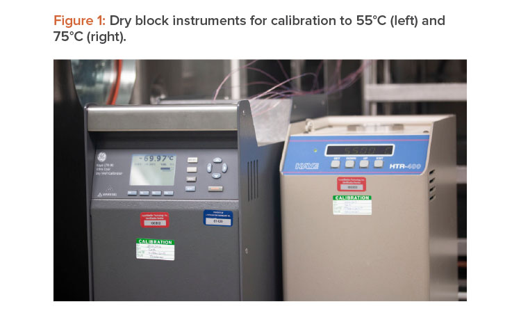
A dry block is composed of a well-insulated metal block in which the temperature is controlled by the use of heating and cooling for precise temperature control. Currently available dry well calibrators provide a combination of portability, accuracy, convenience, and stability relative to a liquid bath. Such systems may have the capability of spanning very low to relatively high temperatures, such as –100°C to 400°C. Their portability and ease of use make them ideal for field calibration. A separate temperature sensor, such as a high-accuracy resistance temperature detector, may be used as a working standard temperature reference. Commercially available dry well heating and cooling blocks, as shown in Figure 1, have multiple wells for holding thermocouples and resistance temperature detectors, resolve temperature to within 0.01°C, and are temperature stable to within 0.02°C.
Pressure Calibration
Pressure within the lyophilizer chamber varies widely during different stages of the process; it may be as high as 35 PSIA during steam sterilization, and as low as 20 µm Hg during primary and secondary drying. Because the pressure ranges are significantly different, specific instruments are needed to monitor and control them.
Low-Pressure Sensors and Calibration
Two types of pressure sensors are commonly used on lyophilizers for the low-pressure ranges during primary and secondary drying: capacitance manometers and thermoconductivity (Pirani) gauges. Of the two, capacitance manometers are the more commonly used, as they provide a direct pressure measurement independent of the gas composition of the environment.13 In addition, capacitance manometers used on lyophilizers are often heated and controlled at a specific temperature (100°C–200°C) to prevent water vapor from condensing on the sensor. The heated transducer also eliminates temperature influence of the environment on the sensor.
Thermoconductivity gauges use the rate of heat loss of a hot wire to determine pressure and are typically calibrated using nitrogen gas. An error is introduced when the gas composition within the lyophilizer chamber can vary between water vapor, air, and nitrogen, as the vacuum measurement provided by the thermoconductivity gauge may not be an accurate representation of the product chamber’s actual pressure. At the same time, using both a capacitance manometer and a thermoconductivity gauge may be beneficial: As the amount of water vapor in the product chamber decreases during drying, the error in the pressure measurement by the thermoconductivity gauge decreases. A comparison between the pressure measured by the capacitance manometer and the pressure measured by the thermoconductivity gauge may help determine the end of primary drying. 14
A high-accuracy capacitance manometer used as a working standard is the preferred instrument for calibration of capacitance manometers and thermoconductivity gauges.15 The transfer standard is typically incorporated into a bench-top or portable vacuum calibration system, onto which the unit under test is installed. These systems consist of the high-accuracy capacitance manometer and its readout, a vacuum pump, a test port to which the sensor being calibrated is connected, manual pressure control valves or a proportional control valve with pressure controller (for automated pressure control), and stainless steel piping connecting them.
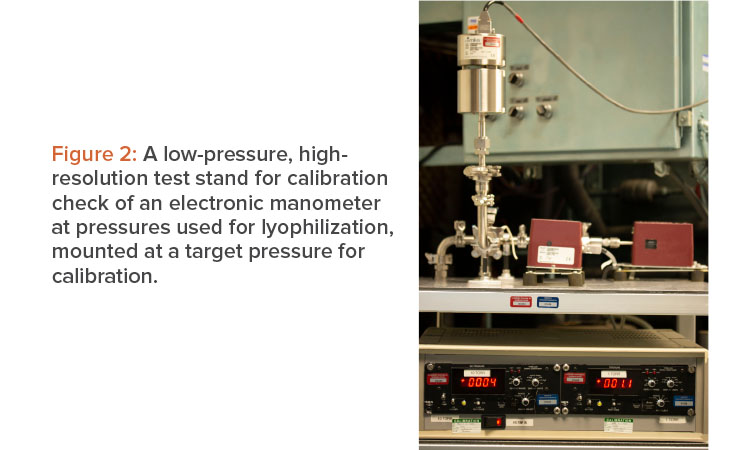
An effective procedure to calibrate a capacitance manometer is to remove it from the chamber and install it on the vacuum calibration system, as seen in Figure 2. To verify linearity, as well as accuracy across the range, it is important to perform a check at a minimum of three pressure setpoints: the lowest obtainable pressure (<1 micron), a midpoint (500 microns), and a high pressure (900 microns). Implementing these checks involves comparing the unit under test to the standard, making necessary adjustments, and rechecking the calibration at a minimum of three pressure setpoints. Once completed, the sensor can be reinstalled on the lyophilizer chamber.
A thermoconductivity gauge may be calibrated in the same way; however, it is important to remember that the thermoconductivity gauge’s measurement is affected by the gas composition of the atmosphere for which it is measuring the pressure. A more rigorous evaluation may be to check the pressure at five different pressures across the instrument range. As an alternative, if there is a difference in any one of the low, midrange, or high pressures for a three-point check and an adjustment is needed, checking the measurement at five points would provide greater confidence in the linearity of the measurement.
It is possible to calibrate a capacitance manometer in situ by connecting the transfer standard to the lyophilizer chamber as close as possible to the sensor being calibrated and using the lyophilizer’s vacuum system to control the pressure at the various test points. The main limitation with this method is the vacuum system on the lyophilizer and the higher potential for leaks make it very difficult to achieve a pressure low enough to zero the unit under test. In addition, it may be difficult to install the transfer standard close enough to the unit under test to prevent the connection length between the two from affecting the pressure measurement.
Calibrating a thermoconductivity gauge in situ may be a good option on a system that has both an electronic manometer and the thermoconductivity gauge. The steps in this procedure are as follows:
- Verify calibration of electronic manometer transducer.
- Ensure the lyophilizer is clean, dry, and empty.
- Chill the condenser to below –50°C.
- Evacuate the lyophilizer to the desired pressure for calibration check.
- Control the chamber pressure to the desired target setpoint by introducing nitrogen.
- Compare the pressure indicated by the thermoconductivity instrument to the electronic manometer.
- Adjust the thermoconductivity instrument as needed to match the electronic manometer.
It is important to allow the conditions in the lyophilizer to stabilize at the desired pressure setpoint long enough to ensure the atmosphere within the chamber is dry and predominantly nitrogen. Upon completing calibration, the thermoconductivity gauge can be compared to the lyophilizer’s electronic manometer readout to monitor the difference that may reflect the presence of water vapor in the lyophilizer chamber. This procedure may be repeated for any additional calibration pressure setpoints and adjustment to the thermoconductivity gauge can be performed if necessary.
PSIA Sensors and Calibration
At the PSIA range of pressure measurement, two commonly used pressure sensors are the piezoresistive strain gauge pressure transducer and the capacitive pressure transducer.16 Both translate the movement of a diaphragm during pressure changes to an electrical output (volts or milliamps). There is no clear advantage of one style over the other; however, it is necessary to ensure that the sensor is made from corrosion-resistant material, such as stainless steel or Inconel, and compatible with clean-in-place/sterilization-in-place systems.
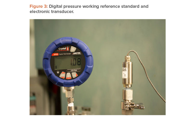
A high-accuracy digital pressure gauge displaying pressure measurements in PSIA is the preferred working standard reference instrument for PSIA pressure transducer calibrations. Using a simple hand pump capable of applying both pressure and vacuum along with the high-accuracy digital pressure gauge (Figure 3) is sufficient for quickly and accurately calibrating either style of pressure transducer.16
To calibrate the pressure transducer, remove it from the chamber and install it on the manifold consisting of an air pump in line with the high-accuracy pressure gauge used as a working standard, ensuring a tight seal between all system components. To verify linearity as well as accuracy across the entire range, it is important to perform a check at a minimum of three pressure setpoints: the lowest obtainable point (e.g., 0.3–1 PSIA), a midpoint at atmospheric pressure (e.g., 14.7 PSIA), and a high pressure (e.g., 35.0 PSIA). Implementing these checks involves comparing the unit under test to the working standard reference, making necessary adjustments, and rechecking the calibration at the same three pressure setpoints checked earlier. Once completed, the sensor can then be reinstalled on the lyophilizer chamber.
Conclusion
Greater knowledge and understanding of the science and technology of lyophilization have led to improvements in calibration, resulting in enhanced process control. The three essential aspects of a well-developed calibration program—methodology, administration, and the calibration itself—inspire confidence in the instrument’s assessment of a measurement’s accuracy and precision.
Proper instrument calibration provides confidence that reported values accurately reflect process conditions. This is critical for process control during batch manufacture and helps ensure that the desired level of product quality is achieved.
About the Authors


