Introduction to Steam Quality and Testing
Steam is the most powerful and effective thermal energy transfer fluid, and its use continues to grow in process industries around the world. However, there is very little written about the commissioning and qualification of pharmaceutical pure steam systems in GMP regulations or regulatory guidance. This article provides the background and science behind the steam quality tests and proposes a risk-based approach to the routine monitoring of steam quality for a system providing steam to all pharmaceutical applications/autoclaves.
Ask anyone about steam engineering, and they will likely think of lumbering locomotives and traction engines from a bygone era. The more well in-formed will know about the role of steam in the Rankine cycle and power generation. But few will know that steam is used in process industries world-wide because it is the most powerful and effective thermal energy transfer fluid. It remains the most powerful and efficient way of controllably transferring heat to the many processes and utilities around a plant. For that reason, in a modern pharmaceutical plant, steam is an essential tool.
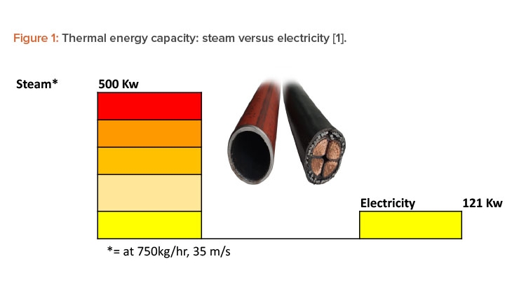
A steam pipe can transfer approximately four times the amount of thermal energy as an electrical cable with an equivalent diameter (Figure 1). Generating steam centrally at moderate pressures allows the use of relatively small pipes, before the pressure and temperature are reduced to suit the process or application.
For saturated steam, there is a defined physical relationship between pressure and temperature that supports good temperature control and ensures that any process is kept within temperature limits.
Because many critical processes in the pharmaceutical industry use steam in direct contact with the product or product contact surfaces (such as during sterilization), it is essential that the use of steam meets regulatory expectations.
The latent heat that steam releases when it condenses into liquid is the greatest of any of the common fluids available. Steam latent heat is relatively constant over a broad pressure range, giving rise to a condensing heat transfer coefficient of between 4,000 and 15,000 w/(m2K).2 It is this combination of controllable temperature and high heat flux that makes steam rapid in response and a highly effective thermal tool.
![Figure 1: Thermal energy capacity: steam versus electricity [1].](/sites/default/files/2022-07/0722_PE_JA_TechHaycocks_01_0.jpg)
Steam-Driven Applications
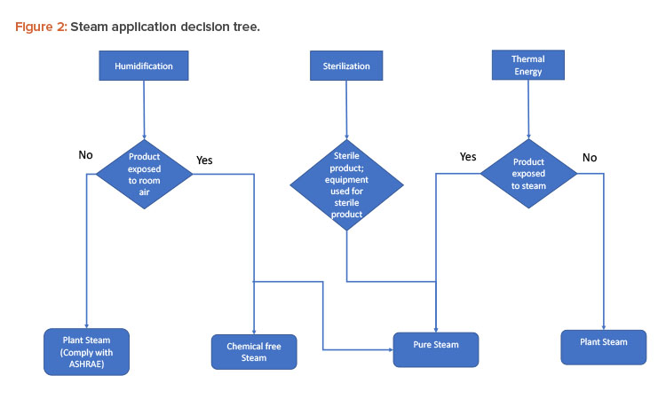
Various processes in the pharmaceutical industry use steam, with different properties depending on the process requirements and the potential risk to product quality. Pharmaceutical steam is classified into three types:
- Plant (utility boiler produced) steam
- Chemical-free (non-utility boiler produced) steam
- Pure (non-utility boiler produced) steam
Figure 2 shows typical applications for the different types of steam.
Plant Steam
Plant steam is used in applications that involve no direct contact between the steam and the product or product contact equipment. It is produced from potable water fed into an industrial-type boiler, where additives are used to raise the pH to 9.5–10.5 to protect carbon steel equipment from corrosion.
It is used as a heat source for non-critical and cGMP heat exchangers for heating (frost protection) coils in heating, ventilation, and air conditioning (HVAC) applications, as well as in critical applications such as water for injection (WFI) production via heat exchangers. It can also be used to sanitize non-product contact equipment or for the biological destruction of solid or liquid wastes in equipment sometimes known as “kill tanks.”
Chemical-Free Steam
Chemical-free steam is similar to plant steam in that is generally used in non-direct contact applications. The key difference is, as the name suggests, that it is produced from pretreated (usually softened) water, meaning it has not been treated with volatile or non-food-grade boiler additives.
Primarily reserved for humidification and nonsterile product sanitization or bioburden control, chemical-free steam is also used for non-critical steps in the manufacture of active pharmaceutical ingredients (APIs) involving no contact with the product. Humidification for HVAC pharmaceutical systems (usually provided prior to the system high efficiency particulate air [HEPA] filter) and bioburden control of early-stage manufacturing equipment both fall into this category. Chemical-free steam provides an acceptable level of purity because any added impurities will be removed in subsequent procedures.
Pure Steam
Pure steam, otherwise known as “clean” steam, is generated from treated water that meets applicable drinking water regulations, USP Purified or WFI classifications, and is free of any additives (amines and hydrazines). It is used for thermal disinfection or sterilization processes as well as equipment sterilization processes (e.g., freeze dryers, process equipment, and pipework) and sterilization using an autoclave or stopper processor.
Pure Steam Quality
The feedwater for a pure steam system must meet local potable water standards. The steam quality, measured as condensate, must meet the relevant specifications for WFI, excluding the microbiological requirements, but including endotoxins. There are national standards and guidelines defining the engineering specifications for steam generation plant and distribution systems, such as those from the American Society of Mechanical Engineers (ASME).3 and ISPE’s Baseline Guide for Water and Steam Systems version 3.4 These will include material specifications, dimensions/tolerances, surface finish, material joining, and quality assurance procedures.
There are also specifications established through European Standard EN 285:2015, Sterilization. Steam Sterilizers. Large Sterilizers,5 for pure steam quality when used for sterilizers:
- Supply steam must have a dryness value of no less than 0.95.
- Obtain no more than 3.5 ml of gases per 100 ml of condensate.
- Superheat to be less than 25°C when expanded to atmospheric pressure.
| Steam Quality Testing Standard | Document Title | Notes |
|---|---|---|
| ANSI/AAMI ST79: 20179 | Comprehensive guide to steam sterilization and sterility assurance in health care facilities |
Higher requirement for steam dryness compared to EN 285 |
| EN 285: 20155 | Sterilization. Steam sterilizers. Large sterilizers | Covers Europe and the UK |
| Parenteral Drug Association (PDA) Technical Report TR110 | Validation of moist heat sterilization processes; Cycle design, development, qualification and ongoing control | TR 61- Steam in Place does not have any relevant content |
| Parenteral Drug Association (PDA) Technical Report TR4811 | Moist heat sterilizer systems: Design, commissioning, qualification and maintenance |
|
| USP 43–NF 3812 | Monograph for Pure Steam | The level of steam saturation or dryness, and the amount of NCGs are to be determined by the pure steam application |
| Parameter | Steam Dryness Value |
NCGs | Superheat |
| EN 285 2015 | > 0.95 w/w | ≤ 3.5 ml/100 ml | > 25 |
w/w = weight per unit of weight.
The requirement for steam quality tests has long been a topic of discussion. Some questions arise from a lack of understanding of the origins of steam testing and how the principles apply to different sterilizer load types: non-porous and porous. Here we aim to explain these quality parameters, and their impact.
The heat penetration for a non-porous load comes from the heat transfer to the item through the outer surfaces; usually the challenge is that in the time taken to heat up the thermal mass, any steam superheat would be dissipated by the mass, and the impact of non-condensable gases (NCGs) would be limited. A porous load, like a filter or a garment, presents a different challenge. In this case, NCGs could create a problem by lodging in the load and acting as an insulator, preventing heat transfer to the inner parts of a load item.
Steam Testing
In the mid-1970s, the UK National Health Service was experiencing a significant number of failures in porous load and equipment sterilization cycles, incurring considerable costs and jeopardizing patient safety. Keith Oates, from the Scientific and Technical branch of the Department of Health and Social Security, was charged with resolving this issue. He discovered that the problem was poor steam quality, for which he developed a means of simulating variation in the quality parameters and supporting tests to measure the levels of the quality parameters.6 His work was incorporated into Hospital Technical Memorandum (HTM) 10, published in 1980,7 as diagnostic tools that included the test methodology for determining dryness and NCGs.
HTM 10 was replaced by HTM 20108 in 1994: Oates was one of the principal authors and the Work Group Convener for the original version of EN 285: 1996,5 which included the steam quality tests, with the associated test methods and acceptance criteria.
With the publication of HTM 2010,8 the Medicines and Healthcare Products Regulatory Agency (MHRA; MCA at the time) recognized that the issues impacting sterilizers in hospitals would have a similar impact on sterilization in the pharmaceutical industry. MHRA began to apply the same steam quality criteria when inspecting manufacturing companies domestically, as well as in their role as European Medicines Agency (EMA) inspectors. Although HTM 2010 [8] may have originally been cited as a reference, this practice appeared to cease on the publication of EN 285: 1996.5 (EN 285 was updated in 2015 and 2021.)
Steam testing and the introduction of specific criteria became accepted; both are now a standard practice. Currently the standards for steam quality testing are defined in a number of documents, shown in Table 1; however, each differs slightly.
The pharmaceutical/biotechnology industry typically references EN 285: 2015,5 which has the requirements listed in Table 2.
For laboratory autoclaves, >0.90 w/w is considered acceptable.
EN 2855 and HTM 20108 refer to dryness as a unitless value. The term w/w is properly used when describing the dryness fraction. It should be noted that the NCG limit has changed in
EN 285: 20155 and is no longer represented by a percentage.
Various aspects of the system design and installation impact the system’s ability to meet the requirements; therefore, it is imperative to design and install systems properly. Each quality requirement is discussed further in the next section.
Steam Dryness
Steam dryness is important, because wet steam can cause wet loads, with consequent risks to sterility if products are stored wet. Wet steam also has less enthalpy than dry steam, so a greater quantity is required to provide the equivalent heat energy. Moisture droplets can also damage pipework and valves.
Dryness value is primarily a function of the distribution system design/demand at the time of testing. Testing for dryness around the steam distribution system at critical points is a valuable way of confirming that a steam system has a competent design and is being well maintained.
Dryness Fraction
The term “dryness fraction” implies an absolute and exact mathematical measurement of the mass of water contained in a given mass of steam. The term “dryness value,” however, is used to describe the amount of moisture present based on the EN 285/HTM 20105, 8 methodology, which is not exact.
A well-designed steam generator produces steam with a dryness fraction of 1. Many generators will include or recommend that a separator is fitted immediately downstream of the generator outlet to ensure such a dryness fraction is achieved.
By definition, 100% dry saturated steam with a dryness fraction of 1 is steam that is at its condensing point and, as such, in a transient condition. Any heat loss will result in condensate being generated and the steam becoming wetter. Maintaining steam in a condition that is as dry as possible requires good engineering design and practice throughout the steam distribution system.
Condensate
As soon as the steam leaves the generator, it is distributed through a metallic pipework system that is kept hot by the heat gain due to the steam condensing on the walls of the distribution system. The pipework is kept at a temperature close to the steam temperature, though there is a small temperature loss due to the boundary layer. Some of the condensate from the pipe walls will be picked up by the steam being transported through the system. There will be more condensation if the insulation is poor or damaged, and more condensate will be carried by the steam, if the system has a poor fall or slope, or if it is inadequately drained. If the steam consumption increases, there will be less condensate proportionally. Typically, steam systems have a small rivulet of condensate which is removed by steam traps placed throughout the piping system.
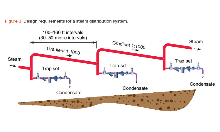
A well-designed distribution system has a slope of not less than 100 mm per 10 meters of pipe (1:100) in the direction of steam flow, with steam traps installed in pockets at 30- to 50-meter (90- to 150-feet) intervals to remove any condensate that has formed. Usually the condensate, which is small in volume, flows at the bottom of the pipe. This small bead or rivulet is removed from the system via the condensate trap, which is installed in a small tee off the bottom of the pipe (Figure 3). If steam headers are used, they should be installed with the correct drainage angle to a steam trap to prevent any pooling of condensate.
It is good engineering practice to fit a separator just before the connection to the sterilizer to ensure as much condensate is removed as possible. Condensate in any pools can be picked up by higher steam velocities as they occur through the sterilizer cycle. Additionally, an inline separator can re-move any entrained water/condensate. Suspended water droplets are impinged on a series of baffles before flowing via gravity into a drainable outlet trap. Separators installed immediately before or after the valve are a simple but effective solution and typically remove more than 99% of condensate.
Test Sample
Per EN 285,5 the quality test sample should be taken from the center of the pipe and should be representative of the quality of the steam being used in the system. However, it is not representative of the overall steam quality at that point, and as such it is known as the dryness value. Overall steam quality can be measured by using a static mixer to mix all the condensate together with the steam and measuring close to the mixing point.
In this case, a sample will be representative of the overall system steam condition at that sampling point and is known as dryness fraction. With well-functioning steam traps and separators, condensate at the bottom of the pipe will be removed, so a measurement from the center of the pipe may be considered representative.
Dryness as a Diagnostic
Accurately measuring steam dryness fraction can be a very useful diagnostic of the overall health of a steam system. A low fraction value can have a number of causes:
- Damaged/degraded insulation on the steam distribution system
- Inadequate drainage of the distribution system due to insufficient fall/slope
- Pipe sagging
- Dead legs (sections of piping that do not allow steam to flow)
- Steam velocity (demand)
- Insufficient drainage slope on steam headers
- Malfunctioning steam traps/separators, preventing effective condensate removal
- Inadequate/poorly located steam traps, preventing effective condensate removal
- Clogged steam filters (if they are used), causing an unusually high pressure drop that reduces steam flow
- Poor steam generator maintenance or operation
Impact of a Low Dryness Fraction
Wet steam can cause wet loads with consequent risks to sterility if products are stored wet. Wet steam has less enthalpy than dry, so a greater quantity is required to provide the equivalent heat energy. Moisture droplets can also damage pipework and valves.
Dryness value is primarily a function of the distribution system design/demand at the time of testing. Testing for dryness around the steam distribution system at critical points is a valuable way of confirming that a steam system has a competent design and is being well maintained.
Commissioning, Testing, and Monitoring
Testing is required for steam sterilizers. If the pipework design is similar in terms of the design (length of pipe run/fall, steam trap types and location) per sterilizer connection, then a reading on the index run is all that is necessary. But as the pipework typically varies for each connection, each autoclave connection is typically tested for dryness value during commissioning/qualification.
Non-condensable Gases
Non-condensable gases (NCGs) are gases that are entrained in the steam during generation. Air and other NCGs act as an insulator and should therefore be minimized in pharmaceutical steam systems. Such impurities offer a highly effective barrier to steam penetration and heat transfer, resulting in a reduced load temperature or absence of moisture at the interface with the load. With porous load (such as gowns), the gas may prevent penetration of the load, and could mean lower temperatures for system components or process equipment, potentially leading to incomplete sterilization.
Thermostatic steam traps are placed within the distribution system in positions where air is prone to collect, such as the terminal points of the main and large branches of the steam header. Working on the basis that air is heavier than steam in the distribution system, the traps separate and remove the NCGs to improve the quality of the steam. Although this is true under static conditions, when steam is flowing, NCGs will travel in the direction of flow. Good practice is to also fit air vents at the end of branches and at system high points, because excessive levels of air may slow down the discharge of condensate. Excess water from subcooled condensate can cause insufficient sterilization temperatures.
NCGs are a function of the feedwater quality and the effectiveness of any degassing system. Whether through preheating feedwater and allowing it to vent, or through the use of a separator on the generator, the levels will vary depending on feedwater quality and on the system state and flow rate. It should also be noted that levels may be higher after a period of nonuse (e.g., overnight). Even small amounts of NCGs can accumulate in the steam distribution system and can subsequently be pushed out as a large volume on startup. This is mitigated in a well-designed system by ensuring the steam distribution system has proper air venting arrangements.
For a steam in place (SIP) system (this would include a tank or lyophilizer), the efficacy of the design for the vents and system drainage are confirmed during commissioning. The location of the cold spot is typically identified and used for ongoing monitoring or periodic performance assessment. This is considered adequate control and it is not necessary to confirm NCG levels for a steam system feeding an SIP system.
High NCG Value Causes
High NCG values can be caused by a number of conditions:
- Air ingress into the distribution system (e.g., if the system is shut down overnight, a vacuum will form as it cools potentially pulling in gases). A preoperational cycle on the autoclave can help manage this by flushing the system with steam.
- Inadequate venting of the steam distribution (or, in the case of SIP for a pipework system, inadequate venting of the pipework system).
- Inadequate de-aeration of the steam generator feedwater/degassing of the steam.
- Leaking glands on steam valves that allow the compressed air used for the valve actuators to enter into the steam system.
High NCG Impact
NCGs are released when the steam condenses. For an autoclave, this is at the interface with the load. Therefore, as more steam comes in to fill the void created by the change in volume created by steam condensing, more gas is released. The gas creates insulating pockets, preventing the surface of the load reaching temperature. Degasification either at or downstream of the steam generator can easily rid the system of NCGs. There has never been a product quality issue cited due to NCGs; however, NCGs will not appear in a root cause analysis if there is no knowledge or understanding of them. A typical scenario is where there is a failure(s) of a biological indicator (BI) and the response is to increase a sterilization time way in excess of that which should be necessary to inactivate the BI.
Commissioning, Testing, and Monitoring
NCGs are a function of the feedwater quality and particularly of temperature, system state and flow rate, the distribution system, venting design, and demand at the time of testing. Testing should be completed for each sterilizer prior to qualification according to the procedure described in EN 2855 to confirm compliance and identify the worst-case location.
If any particular location (typically the index run) on a system consistently gives higher results than other points, then that single point should be verified annually, with all points verified if the result at that point is a failure, or marginal. (This strategy assumes that the original testing was carried out under normal operating conditions, so that the readings are typical.)
For an SIP system (this would include a tank or lyophilizer), commissioning typically maps the system to ensure that there is adequate venting and drainage to obtain uniform temperature distribution. The location of the cold spot is typically identified and used for ongoing monitoring or periodic performance assessment.
Superheated Steam
Superheated steam is steam at a temperature higher than its vaporization point at the absolute pressure where the temperature is measured. It can therefore cool by a certain amount without changing state from a gas to a mixture of saturated vapor and liquid.1 Superheated steam heats or cools convectively, whereas condensing steam heats directly by giving up its latent heat of vaporization. The heat transfer coefficient of the two mechanisms are very different.
As an example, we as humans breathe superheated air. At atmospheric pressure, the vaporization point for air is -194.35°C (-317.83°F). If the ambient air temperature is 20°C, then the air is superheated by 214.35°C (385.83°F).1
The heating convective coefficient at atmospheric pressure is likely to be in the range of 5-100 W/m2°C depending on steam velocity.2 For steam condensing on a flat vertical surface, the value is 4,000°C to 11,300 W/m2°C. Superheated steam is therefore up to 11 times less effective than saturated steam as a heating agent. Although energy transfer plays no part in the F0 (minimum time-temperature; see USP 1229.1) calculation, the rate of the transfer will affect the time required to reach the desired temperature. Fortunately, the amount of energy in superheat in a typical pharmaceutical plant steam system is small and easily dissipated by any wetness or heat transfer to the load requiring sterilization, resulting in saturated steam.
This can be illustrated with the following example: 100% dry (dryness fraction of 1) steam at 7.0 barg (101.5 psig) is passed through a pres-sure-reducing valve to reduce the pressure to 1.037 barg (15.05 psig). Such a pressure reduction is isenthalpic and an adiabatic calculation shows that the steam temperature after pressure reduction would be 149.76°C compared to a saturated temperature at 1.037 barg of 120.8°C—in other words, nearly 29°C of superheat. See Table 3 for other examples.
Although this might seem a large number, it represents less than 3% of the energy available from condensing the low-pressure steam in the sterilizer. In most installations, there is enough residual “wetness” to absorb this energy or sufficient “heat leakage” in the piping before the sterilizer to dissipate any superheat.
Sterilization is achieved from the transfer of heat energy contained in saturated steam through condensation when the load temperature is raised sufficiently to inactivate bioburden loads, proteins, and other potential pathogens; sterilization occurs because of the presence of temperature and moisture. The energy level and rate of its transfer does not play a part in the sterilizing effect. Also, sterilization occurs in fluid loads in the absence of latent heat. Where the steam is superheated, the heat transfer during the initial cooling phase from the superheated steam temperature to the saturation temperature is not as efficient, as it is after the steam cools to the saturation temperature and where condensation occurs—the condensate im-proves the heat transfer raising the temperature, with the time at temperature sterilizing the material.
| Pressure/Dryness Fraction | |
|---|---|
| Before Pressure Drop | After Pressure Drop |
| 5 BarA/0.95 | 3.2 BarA/0.96 |
| 5 BarA/0.98 | 3.2 BarA/0.99 |
| 5 BarA/0.95 | 2.1 BarA/0.97 |
| 5 BarA/0.98 | 2.1 BarA/1.0 |
| 5 BarA/0.98 | 1.0 BarA/at 10°C of superheat |
Potential Issues
Certain conditions may present a problem and must be watched for:
- Steam that is dry saturated (or close to it) can be subject to a significant pressure drop. Note: the risk increases with drier steam and larger pressure drops.
- Jacket temperature or pressure that is too high in an autoclave can effectively superheat the steam as it enters the autoclave.
- Steam flowing through a small orifice or a tight-radiused direction change between its source and the chamber or equipment can cause a large pressure reduction or steam velocity increase with no pipework to allow superheat to dissipate after the fitting/orifice (which could be a valve).
- System cannot maintain adequate pressure. For a simple system, steam is generated at a pressure slightly higher than that required for the users to allow for the pressure losses in the distribution system. For a large installation, the distribution pressure is typically significantly higher to ensure that there is adequate pressure to supply demand when multiple users call for steam at the same time. In this type of design, a pressure-reducing valve will be used on the supply to the use points.
- A poorly designed system will reduce pressure above a ratio (n) of 2:1 and not provide an adequate length of pipework for the steam to equilibrate before going to the control valve. Excessive pressure reduction can result in the steam generating significant superheat. With the more usual ratios, the quality of the steam will change (the process is isenthalpic [i.e., the enthalpy value remains constant], hence the changes in the steam quality).
Steam is one of the most effective mediums to transport thermal energy, but the control and potential impact of steam quality parameters should be understood.
| System Type | Commissioning/Qualification | Monitoring | ||||||
|---|---|---|---|---|---|---|---|---|
| Chem/ endotoxin |
NCG | Dryness | SHT | Chem/ endotoxin* |
NCG | Dryness | SHT | |
| SIP | X | N/A | N/A | N/A | Q | N/A | N/A | N/A |
| LYO | X | N/A | N/A | N/A | Q | N/A | N/A | N/A |
| Autoclave | X | X | X | X | Q | Q* | A | N/A |
| Stopper processor |
X | X | X | X | Q | Q* | A | N/A |
A = annually; LYO = lyophilizer; N/A = not applicable; Q = quarterly; SHT = Superheat. Q* = quarterly initially until data are available to support reduced testing, assumes that the feedwater to the steam generator is routinely monitored.
Good design limits the stage pressure reduction per stage (not more than 2:1 per HTM 2010 Part 2 paragraph 7.208) and allows an adequate length of pipe for the steam to reach equilibrium before it is added to the autoclave chamber. Per HTM 2010 Part 2,8 “where the supply pressure at the inlet to the sterilizer would exceed the maximum value specified by the manufacturer, a pressure-reducing system and separator should be fitted to the supply pipe at least 3 meters from the sterilizer. Heat loss from the section between the pressure-reducing system and the sterilizer will help prevent superheating.”
Note that pure steam generators typically do not have the capability to produce superheated steam. The water is heated and evaporates, passing through a separator to prevent moisture droplets being carried over with the steam. The steam from the generatoris ideally dry saturated steam (with a dryness fraction of 1). The system is not designed to add heat to the steam or to create superheat.
Excess Superheat Impact
For a pharmaceutical system, the quality of the steam from the generator is generally consistent: superheat is a function of the distribution system design/flow rate.
For an SIP system (this would include a tank or lyophilizer), there is adequate pipework or metalwork for any superheat to be reduced. Due to the significant ratio of surface area to volume of the system, commissioning typically also temperature-maps the system to ensure there is adequate venting and drainage to obtain uniform temperature distribution; because of this, it is not considered necessary to measure superheat.
Commissioning, Testing, and Monitoring
For an autoclave, superheat levels can be tested during commissioning. Because the pipework to each system will vary slightly, each autoclave should be tested during commissioning. For an autoclave or SIP system, superheat is usually effectively monitored through the comparison of the temperature and pressure function in the automation. Alarm systems are in place to highlight a significant mismatch. The test regime proposed is shown in Table 4 (and supported by Table 5 in the Appendix that follows this article).
Conclusions
As the article explains, steam is one of the most effective mediums to transport thermal energy, but the control and potential impact of steam quality parameters should be understood. The design and maintenance of the steam distribution system is critical. An appropriate level of monitoring of the parameters should be used to confirm that the steam delivered is within the specified limits. Suggested testing is described in Table 4 (and supported by Table 5 in the Appendix that follows this article).
Appendix
| Potential Failure Mode |
Potential effect of failure |
Severity | Potential Cause |
Likelihood | Design controls | Operational Controls | Detection | Detection | Recommendation | Risk Level |
|---|---|---|---|---|---|---|---|---|---|---|
| Clean steam does not meet specification at point of use. (chemistry, endotoxin & physical properties) |
Ineffective sterilization in steam sterilizers (autoclaves, stopper processers) |
5 | High noncondensable gases |
3 | Clean steam generator supplied with pre-heated water / fitted with degasser function |
Monitoring of degassing critical parameter temperature of feedwater or evaporator temperature in case of integral deaerator) |
Commissioning / qualification testing of capability, and routine monitoring of evaporator or feedwater water temperature (depending on degasser type) |
3 | Initial performance testing at generation and supply to each sterilizer. Routine monitoring at worst-case point through annual testing at furthest autoclave or end of header. |
Low |
| Excess superheat |
1 | Piping design - limited pressure drop per stage with adequate pipework for fluid equilibration |
Company SOPs require the steam supply to be qualified as part of the sterilizer commissioning / qualification. |
Confirmation of superheat levels during commissioning / qualification |
Initial performance testing at steam generator and supply to each sterilizer. Reverification if changes are made to local piping. |
|||||
| 5 | Low dryness (excess water droplets) |
3 | incorporates droplet separator. Distribution system incorporating drainage (falls), trapping, and specified levels of insulation, with a pocket and steam trap on the connection to the sterilizer |
Company SOPs require the steam supply to be
|
Confirmation of superheat levels during commissioning / qualification. Periodic testing at representative sample point |
3 | Testing at generation and supply to each sterilizer. Routine monitoring at worstcase point through annual testing at furthest autoclave or end of header. |
Low | ||
| Product contamination due to high bacterial endotoxin in steam |
5 | High endotoxin feedwater, carried over into steam |
5 | Generation system supplied with endotoxin controlled feedwater. |
Company SOPs require the steam supply to be qualified as part of the sterilizer commissioning / qualification. |
Quarterly sampling of feedwater for endotoxin. |
1 | Quarterly sampling of feedwater for endotoxin. |
Low | |
| 5 | Ineffective separation and removal of endotoxins at generation |
3 | Multi stage impurity separation in clean steam generator, and blowdown to provide consistent feed quality. |
Routine verification (annual) of blowdown volume |
Routine monitoring of pure steam condensate. |
3 | Routine monitoring of pure steam condensate. |
Low | ||
| Product contamination due presence of organic carbon |
5 | High TOC in feedwater, carried over into steam |
3 | Generation unit supplied with TOC controlled feedwater. |
Online TOC monitoring of feedwater |
Alarm from online monitoring instrument |
1 | Continuous monitoring of the system feedwater. |
Low | |
| 5 | Ineffective separation and removal at generation |
3 | Multi stage impurity separation in clean steam generator, and blowdown to remove impurities. |
Routine verification (annual) of blowdown volume |
Alarm from online monitoring instrument |
1 | Continuous monitoring of the generation system condensate, routine testing at representative sample point (pipework index (longest) run) |
Low | ||
| Product contamination due to high conductivity |
5 | High conductivity in feedwater, carried over into steam |
5 | Generation unit supplied with conductivity controlled feedwater. |
Online conductivity monitoring of feedwater |
Alarm from online monitoring instrument |
1 | Continuous monitoring of the system feedwater. |
Low | |
| 5 | Ineffective separation and removal at generation |
3 | Multi stage impurity separation in clean steam generator, and blowdown to remove impurities. |
Online conductivity monitoring of feedwater |
Alarm from online monitoring instrument |
3 | Continuous monitoring of the generation system condensate, routine testing at representative sample point (pipework index (longest) run) |
Low |
| Rating | SEVERITY of the effect of failure (System/Equipment ) |
Likelihood of OCCURRENCE |
Ability to DETECT the failure |
|---|---|---|---|
| 9 | Severe: Serious impact to QA of the output of the system/equipment and impact to final product quality attribute |
Frequent: Failure is almost inevitable Consistent failures observed |
Absolutely uncertain: Existing controls cannot detect the failure; no controls are in place |
| 7 | Major: Significant impact to QA of the output of the system/equipment and possible impact to final product quality attribute |
Likely: Failure is likely and will occur in most circumstances. Repeated failures observed | Remote: Remote chance that controls will detect the failure. A control may be in place but is untested or unreliable |
| 5 | Moderate: Possible impact to QA of the output of the system/equipment and no impact to final product quality attribute |
Occasional: Failure is probable at some time and has been observed | Moderate: A moderate chance that the control will detect the failure |
| 3 | Minor: Minor impact to QA of the output of the system/equipment and no impact to final product quality attribute |
Unlikely: Failure could occur at some time. Only isolated incidents observed | High: Very likely that the control will detect the failure |
| 1 | Insignificant: No Impact to QA of the output of the system/equipment and no impact to final product quality attribute |
Remote: Failure is extremely unlikely. No history of failure | Almost certain: The control will detect the failure in almost every |
| Severity Rating | ||||||
| 1 Insignificant |
3 Minor |
5 Moderate |
7 Major |
9 Severe |
||
| Likelihood Rating | 9 - Frequent | Medium | Medium | High | High | High |
| 7 - Likely | Low | Medium | High | High | High | |
| 5 - Occasional | Low | Medium | Medium | High | High | |
| 3 - Unlikely | Low | Low | Medium | Medium | High | |
| 1 - Remote | Low | Low | Low | Low | Medium | |
| Detection Rating | ||||||
| 1 Almost certain |
3 High |
5 Moderate |
7 Remote |
9 Nil |
||
| Rating from Table 7 | High | Low | Medium | High | High | High |
| Medium | Low | Low | Medium | High | High | |
| Low | Low | Low | Low | Medium | Medium | |
About the Authors