GMP Implementation of Online Water Bioburden Analyzers

Online water bioburden analyzers (OWBAs) are analytical instruments providing real-time or near real-time measurement of bioburden in purified water systems.
OWBAs predominantly use laser-based fluorescence to detect and enumerate microorganisms in a flowing column of water.4, 5 In the pharmaceutical industry, this technology could have value in operations that require high-purity water of a specific microbiological quality. However, implementation of OWBAs into GMP service has been relatively slow due to concerns about using the instruments in a GMP-compliant manner. If OWBAs can be introduced into a GMP environment, there is the possibility of at least reducing the need for grab samples, which are currently used to ensure ongoing acceptability of water. An ultimate aspirational goal is for OWBAs to function in conjunction with online conductivity/total organic carbon (TOC) meters to allow continuous monitoring and real-time release of high-purity waters for GMP use.
Current Technology
A few technologies are currently being used as a basis for online water bioburden detection and enumeration (Table 1). Of these, the technology with the broadest commercial availability is laser-induced autofluorescence. These instruments rely on the intrinsic fluorescence of certain biomolecules inherent in microorganisms. Laser diodes emitting at a specified wavelength of light are used to illuminate a slipstream of water. Microorganisms present in the water absorb this light and release the energy as fluorescent light at a less-energetic wavelength. This light is detected and quantified in auto-fluorescence units (AFUs). One advantage of laser-induced autofluorescence instruments is that the assay is nondestructive, which means the detected bioburden can be captured and grown for identification.
As noted in Table 1, non-laser-induced autofluorescence-based analysis technologies are commercially available or in development. The approach to installation, validation, and approval as described in this article also applies to them.
| Technology* | Detection/Analysis Method |
|---|---|
| Laser-induced autofluorescence | Flow-through continuous measurement |
| Dye-based flow cytometry | Sample-based measurements |
| Lab on a chip (currently in precommercial development) |
OWBA |
AFU Versus CFU Counts
In all fluorescent dye and laser-based systems, there is a natural difference between AFU counts and counts of colony-forming units (CFUs) by traditional plate count methods. In addition to CFUs, AFUs can also include viable but nonculturable (VBNC) cells, debilitated and recently deceased microorganisms, and extraneous bits of materials that also fluoresce at the monitoring wavelength(s). The fluoropolymers in products such as Teflon and Viton and other polymers can fluoresce at these same wavelengths. These materials and microorganisms have historically been present in water samples, but they were not previously quantified, either because they were not tested for (the materials) or because they did not produce visible colony growth (VBNC microorganisms).
Because AFUs measure heretofore undetected microorganisms and materials, CFU and AFU counts cannot be assigned a standard offset. Nevertheless, certain trends are generally, though not definitively, correlated between the CFU and AFU data, and, for this reason, statistical process control (SPC) may be applied to these data. This approach has the benefit of allowing both the traditional and alternative methods to be used in concert with each other, informing the appropriate microbiological sampling activities to be undertaken when upward trends in autofluorescent particles are detected.
OWBA Applications
Understanding the scope of justifiable OWBA implementation is a key factor in a smooth and successful implementation of OWBA monitoring in a facility. Specifically, one must understand:
- The pathway for validation and regulatory acceptance of an alternative microbiological method that detects more objects than the compendial method it is intended to supplant
- The scope of the testing that can and cannot reasonably be replaced with an OWBA
- The requirements imposed as a consequence of OWBA implementation into systems with high regulatory standards and expectations, such as water for injection (WFI) systems
It is also important to understand that the bioburden in a water system may not only be composed of homogeneously distributed microorganisms but also may include nonhomogeneously distributed microorganisms in the form of biofilms. These biofilms can release bacteria into the free-floating state and can slough off in large mats. OWBAs can detect free microorganisms and mats. The fact that bioburden is not homogenously distributed in a water system should be considered when performing a risk assessment–based analysis of the feasibility of reducing sampling frequencies.
It is reasonable to rely on an appropriately validated and regulatorily accepted OWBA as a continuous monitor of GMP water quality on a loop. Just as online TOC and conductivity meters have allowed facilities to reduce the number and frequency of water samples used for monitoring TOC and conductivity, OWBAs act as continuous monitors that, with appropriate trending analysis and risk-based assessment, offer the possibility of reducing the number and frequency of loop water samples.
However, it is not reasonable at the current time to believe that an OWBA can fully replace loop samples, as the OWBA’s meter readings must be periodically compared to data from classical water testing methods to ensure ongoing control of both the loop and the meter. Continued monitoring, system characterization, and regulatory buy-in may allow future wholesale replacement of loop grab samples.
An OWBA monitoring the loop will also not replace required point-of-use (POU) samples due to the potential influence of the piping between the loop and the POU. It would typically be impractical to manifold POUs to an analyzer. It is, however, possible to set up a meter to read in both online and sample injection modes. In this way, a meter could be used in both continuous monitoring and POU sample modes. This approach is not as straightforward as it might seem because introduction of artifacts through injected grab samples is a significant concern. Two recent publications11, 12 review the sources of grab sampling and analysis artifacts and discuss methods for minimizing them in OWBA analyses. There are practical challenges in switching from online to sample injection modes that must be overcome. Among these are ensuring that there is no backflow into the loop and ensuring smooth and consistent injection events.
Regulatory standards and expectations regarding the water quality analyzed by the OWBA dictate the required level of scrutiny that must be applied to OWBA data and installation. OWBA implementation in less-stringent scenarios is relatively straightforward. An example would be purified water. The regulatory limits for purified water are ≤100 CFU/mL. There is a gap between the limit of detection (LOD) of a typical OWBA and the point at which the sensors become overloaded by the amount of signal present. Typical purified water specifications are within this range, so the gap allows a bandwidth in which an OWBA system can operate. Because OWBAs detect more than classical CFUs, the precision of the OWBA measurement, as compared to classical compendial methods, has an inherent span of uncertainty within the operating range. Monitoring could be performed on an SPC basis with event-triggered capture of water samples for microbe identification in the case of an exceeded limit. As one is inherently dealing with higher limits and larger numbers of microorganisms in low-stringency applications, the chance of missing capture of an excursion would be relatively low.
It should be appreciated that water samples that are too low in microbiological quality may have so many detection events that the analyzer be-comes either saturated or nonlinear. Untreated surface water, sewage, and untreated drinking water would not be good candidates for analysis with currently existing OWBA options.
Application of OWBAs is possible in waters with the most stringent requirements (e.g., WFI, which has a regulatory limit of ≤10 CFU/100 mL). However, it is especially difficult in these high-stringency applications to demonstrate control and capture and identify contaminating microorganisms. De-pending on the inherent background AFU detection level (including detection of artifacts like Teflon and Viton particles), the in situ LOD of a typical OWBA on a given high-stringency loop may not be sufficient to adequately resolve microorganism concentrations to the required levels: unless the background AFU level in the water is very low, the analyzer might not be useful for detecting whether CFUs exceed the regulated limits. Those considering such an application should pre-assess whether their system’s inherent background AFU count would allow detection of microorganisms at the required levels. The low numbers of putative microorganisms in these waters must be captured for identification to exclude objectionable microorganisms and ensure knowledge of the type of microorganisms in the water. As a result, such installations require a robust and thoroughly tested capture system for excursions.
Return on Investment
OWBAs have the potential to reduce ongoing costs in facilities. For example, they may help reduce energy usage by optimizing sanitization cycles, reducing water sampling and associated testing costs, and potentially reducing the number or duration of water-associated process deviations. The following are hypothetical examples of OWBA costs and potential savings:
- Instrument purchase, installation, and full qualification: ~$180,000
- Savings from reducing sampling and testing frequency from daily to weekly: ~$30,000/year/sample point
- Energy cost savings through sanitization every second day instead of daily: ~$55,000/year
- Savings from reducing the number of investigations: ~$20,000/event
Any actual evaluation of individual costs, savings, and return on investment should be based on the details of the planned installation.
Installation Guidance
OWBAs can be installed on purified water systems. Care should be taken to ensure that installation does not compromise the GMP status of the system and the water produced by the system. This typically means ensuring that the OWBA is sampling a slipstream that goes to drain subsequent to the OWBA instrument (i.e., the water is not returned to the loop and the slipstream is not subsequently used for GMP purposes).
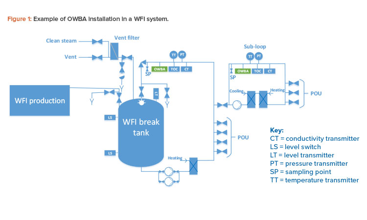
Figure 1 depicts OWBA installation in a WFI system with a main loop and subloop. OWBAs can be installed in other steps in water systems to meet user needs; however, the following points apply:
- The optimal installation point on a water loop to cover and represent the loop is at the return of the loop.
- The OWBA can directly replace some process control (PC) sampling at loop return.
- The OWBA can reduce PC sampling to some extent.
- An OWBA installed in a loop cannot cover the POU directly and therefore cannot, by itself, substitute for quality control (QC) sampling of the POU.
It is reasonable to accept that demonstrating continuous PC can lead to a reduction in loop QC sampling.
The following are other issues that must be considered and/or addressed when choosing where to install OWBAs:
- The cost of having an OWBA installed at each POU would be tremendous and would often cause more trouble than benefit due to issues related to installation space, process equipment functions during sampling, and other factors.
- Because OWBAs use sensitive measuring technologies, there is a high risk that the instruments could be damaged if they are moved. This may be a substantial concern if the intent is to use an OWBA at multiple locations (e.g., moving it to various POUs).
- Using one OWBA to cover multiple POUs would require a multiport valve and connecting piping system. This is seen as a difficult alternative to achieve due to the cross-contamination risks and complex validation requirements.
- Grab sampling at the POU and conducting analysis through an OWBA external sample port presents problems that are not readily obvious. Primarily, this effort could inadvertently introduce particulates or other artifacts during sampling, sample prep, and/or sample injection. Recent publications have addressed methods and points of concern for minimizing artifacts in OWBA grab sample collection and injection.11, 12
- Installing a non-GMP instrument on a GMP system, even if it samples a slipstream that goes to drain, can result in inspection questions.
Product (Water System) Risks
Connection of an OWBA on a water system raises the risk of backflow or microbial growth in tubing. It is therefore important to understand and minimize such risks and determine whether a temporary or continued connection requires a change request.
A change request may not be necessary (depending on local requirements) if changes are not made to the water system. An example is a temporary connection of a silicone tube to a sample valve (or drain valve) to mount the OWBA equipment without any intervention on the system itself (loop, valves).
Materials used for connections must be approved and cleaned. Examples of suitable materials are silicone tubing (the same material that is often used in production); fluorinated ethylene propylene (FEP) or perfluoroalkoxy alkane (PFA) tubing (equivalent to polytetrafluoroethylene [PTFE] tubing); stainless steel cooling coils (supplied by the OWBA supplier to provide an analysis temperature compatible with the instrument); and stainless steel fittings.
There is no risk of liquid backflow if the OWBA cannot produce a higher pressure than the supply pressure. This ensures that there is no overpressure in the OWBA system itself and no overpressure in the loop.
The single and greatest backflow risk is a blocked drain. If the drain is installed with “open” flow, there is no risk of backflow. This can be ensured with an air gap.
Any internal pump used in conjunction with an OWBA must be installed and hardwired to ensure that the pump cannot accidentally change flow direction.
Instrument Qualification
Standard instrument qualification practices as required in relevant internal and regulatory guidances are used to perform instrument qualification. The standard user requirement specification (URS) published by the OWBA Working Group6 is recommended as a foundational document for the instrument qualification. Its use helps ensure that no appropriate requirements are overlooked. However, users are cautioned that local requirements may require additional specifications beyond those in the URS. If the user has additional specific user requirements, it is necessary to carefully consider the characteristics and capabilities of the specific OWBA to ensure that the requirements can be fulfilled. OWBAs are “off-the-shelf” instruments and should generally not be custom redesigned to fulfill specific user needs or wishes.
OWBA-Loop Connection
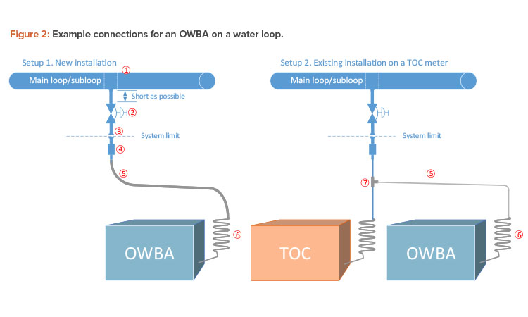
Connecting an OWBA to a loop is relatively uncomplicated. It is recommended that flexible tubing is used from the connection outlet to the OWBA. During engineering studies, the connection could be temporary, using an existing outlet if one is available. Figure 2 shows two examples of how the analyzer could be connected to the loop.
The following are points for consideration regarding components and design (note that for reference, the points are labeled in Figure 2):
- When a new valve is installed, it is preferable to cut the loop and install a “T” piece or expanded “T.” This will ensure proper sanitary design.
- A valve must be installed on the loop so the water supply to the OWBA can be cut off. The valve could be a manual valve, or an automatic valve or a manual valve with automatic override could be considered, especially for long-term installations.
- The valve outlet should be finished with a clamp connection, preferably a mini tri-clamp ferrule connection. This connection will also serve as the system boundary. This means that the components and piping (Figure 2, parts 1–3) will be a part of the water system; therefore, standard installation requirements or GEP must be fulfilled according to company’s requirements for
- Piping and instrumentation (P&I) diagrams and component/instrument data
- Construction materials
- Welds
- Surface roughness
- Sanitary components, instruments, and bulk goods
- Dead legs
- Drainability
- Initial cleaning
- Pipe marking
- Insulation and cladding
- The next component consists of a mini tri-clamp connection and a fitting to connect the flexible tube. The fitting may need to be custom designed because a sanitary component (the mini tri-clamp ferrule) is coupled with a nonsanitary component. However, if a sanitary quick clamp–to–compression tube fitting is used for the nonsanitary component, a custom design is not needed because this is an off-the-shelf component. These couplings often use metal gasket face seal fittings, which are also often used on TOC instruments. So, even though this arrangement is not considered a fully sanitary design, it is probably the best design option available.
- Flexible tubing should be used to ensure the optimal inner surface roughness. The recommended types are transparent; therefore, it is necessary to block out light. Simply take a piece of larger-diameter black tubing and run the PFA/FEP tubing through it so that it is fully covered. To ensure proper drainage and support the tubing, pipe supports can be installed. Given the risk of particle shedding, tubing must be a part of planned maintenance; changing tubing on a yearly basis is also recommended.
- The spiral coil, which is often a part of the purchased OWBA package, is required to help lower inlet temperature because some OWBAs are sensitive to higher temperatures. The OWBA may be able to operate in temperatures up to 40°C. It is important to mount the coil as close as possible to the OWBA equipment to ensure that most of the flow path will be sanitized. Sanitization of the flow path should be a part of routine water distribution sanitization. The frequency and method to be used will depend on the characteristics of the water system and construction materials.
- The “T” piece (Figure 2, part 7) is inserted in existing tubing/piping for the existing TOC instrument. This installation might be an easier alternative compared to a new installation. Stainless steel compression fittings are recommended.
Points 4 through 7 should comply with installation requirements or GEP, according to company’s test/validation strategy for the following:
- P&I diagrams and component/instrument data
- Construction materials
- Surface roughness
- Drainability
- Pipe marking
Wiring and Signal Interfaces
When implementing an OWBA, it is very important to determine how the data will be transmitted from the unit. The two primary means to send data from the unit are (a) via a 4-20 mA connection and (b) use of a transmission control protocol/internet protocol (TCP/IP) connection. The important difference between the two relates to the scale of the data that will be trended. A 4-20 mA connection is typically an easier connection to support, as most processing equipment use this data transmission method and it can be easily integrated into the automation process. The limitation with using this method is the decreased sensitivity or scale associated with this method. For example, with data that range from a baseline average of 300 AFUs to a potential peak of over 100,000 AFUs, the 4-20 mA method will reduce the sensitivity at the lower end to accommodate the higher counts, thus losing the capacity to differentiate changes at lower counts. Furthermore, because significant differences in counts from one loop to another are experienced, permanent default settings may not be appropriate for all or most water loops/systems. Defaults settings may not result in the accuracy that end users are expecting. If analog is still chosen, tailoring output ranges to suit the specific system is recommended. This should be done to some extent to optimize accuracy.
If digital inputs are available on the OWBA, it is recommended that the inputs be used to start and stop sampling on the OWBA. This will allow external control of the OWBA from a supervisory control and data acquisition system. This feature can benefit the user during start-up of the water system.
IT Considerations
The instrument must be compliant with 21 CFR part 11 and EU Annex 11. Before operational qualification can be started, the company must assess whether the OWBA instrument presents a risk to the company’s IT system and how OWBA use can comply with the company’s IT conduct regulations. For example, the instrument may be designed to transfer data via a portable storage device (e.g., USB drive) but the company prohibits use of such devices. As data integrity awareness penetrates the marketplace, these disconnects between instrument requirements and user restrictions should diminish or disappear.
Computer validation is required because all data are generated and handled in the OWBA system software. The analyzers typically generate a large amount of data. This validation process includes specification of user requirements, specification of functional requirements, development of a test plan, execution of the test plan, and demonstration that all requirements have been fulfilled. Data integrity should also be evaluated given its prominence in recent regulatory audits and discussions.
Method Validation
The final required element before the OWBA can become operational is method validation, which also constitutes performance qualification because the instruments are intended for continuous monitoring. For an overview of the method validation process, see the 2018 Pharmaceutical Engineering article by Nissan Cohen.7
Several guidance documents are relevant to OWBA method validation, including ICH Q8(R2).8 Additionally, because OWBAs are an alternative microbiological method, it is important to refer to USP<1223>: Validation of Alternative Microbiological Methods,9 which provides overarching guidance for method implementation. For companies producing for the European market, European Pharmacopoeia Chapter 5.1.610 applies, and for all markets, the Parenteral Drug Association’s Technical Report 3311 provides guidance on implementation of rapid microbial methods.
Fundamentally, these guidance documents require demonstration that the alternative assay method is not inferior to the compendial methods it is intended to replace. This hurdle is not to be taken lightly: Because OWBA instruments report AFUs and compendial methods report CFUs, comparison of the methods, outside of highly controlled experiments12, 13 is typically only possible using statistical trending methods.
Setting Limits
Once an OWBA is installed, qualified, and validated, an extended period of operation is needed to characterize the behavior patterns of the system being monitored. This data set will be useful in delineating definable bioburden-independent changes in OWBA response. As an example, during sanitization cycles, the elevated temperatures in the water system may trigger the OWBA to report an apparent increase in AFUs. Conditions that are clearly definable as not being dependent on bioburden levels may, with documented justification, be excluded from routine ongoing bioburden trend analyses.
An extended period of monitoring is also needed to provide sufficient statistical robustness of the data set used for analysis. Simple rules of thumb, such as a minimum of 30 observations being sufficient for characterizing normally distributed data, do not take into account potential longer-term variations such as seasonal variation. For this reason, it is suggested that preliminary provisional limits may be calculated after a reasonable period (determined by a risk assessment that takes into account a number of factors, including frequency of sampling and known operational impacts to a system); however, OWBA system action and alert limits should be reassessed on a routine basis. Demonstration of ongoing system control may be shown through SPC principles.14, 15
Regulatory Hurdles
Although OWBAs clearly have utility and can be installed, qualified, and validated for use in GMP service, there are regulatory hurdles to their wide-spread implementation:
- As noted previously, OWBAs report units that are different from, and not directly correlated with, the units used in traditional methods. This raises concerns for regulators and inspectors. In turn, companies have internal concerns that agencies might not approve OWBA technologies or products re-lying on such technology, and these concerns can result in delays or supply disruptions. In fact, the relevant compendial chapters provide clear pathways to adoption of alternative methods, including those that use different methods of measurement.
- OWBA validation methods will vary from those used for traditional instruments because OWBAs detect more objects typical of water streams than those enumerated by classical plate count methods (e.g., VBNC microorganisms, dead microorganisms, and polymer particles that fluoresce at the same wavelength as bacteria). We propose that validation via the compendial chapters and demonstration of control via SPC methods are suitable means for demonstrating continued control.
- There is a lack of clear guidance as to how or where to file the use of OWBA technology. In the case of a new installation, a properly installed and qualified OWBA could be incorporated into the facility from the ground up and could be qualified and documented as part of initial water system qualification. Implementation in existing facilities is more complicated due to the need to pilot the instrumentation to collect data and set limits, while not affecting the GMP status of the water system and, by extension, the products manufactured with that water. The FDA guidance on process analytical technology16 addresses how to implement instrumentation into GMP systems for the purpose of evaluating and qualifying the instrumentation. OWBA technologies are used primarily for environmental monitoring of facilities; therefore, we propose that the site master file is the appropriate place to file the use of these technologies in existing facilities. If the technology is officially listed on filed and previously reviewed documentation, it should be less of concern for regulators. This approach should therefore reduce company fears that individual inspectors who are unfamiliar with OWBAs might feel compelled to do a complete re-review of the technology at each inspection. Appropriate change control and notification procedures for incorporating the OWBA into the site master file should be followed to remove risk to continued production.
Conclusion
With appropriate implementation and validation, OWBAscan function as real-time monitors of water system quality and operation. Implementation of OWBAs should follow a classical instrumentation qualification, operational qualification, process qualification (IQ, OQ, PQ), and method validation format. OWBA applications must take into account the stringency of the specifications and the quality of the water being measured. Current regulatory concerns regarding OWBA implementation can largely be resolved through early and frequent dialog with the relevant regulatory authorities prior to using the instruments for GMP purposes.
About the Authors


