

Room Differential Pressures in Facility Design: Fundamentals

The expectations for room differential pressures to maintain air quality in pharmaceutical facility design are consistent and well defined from a regulatory perspective. However, there is no common approach to the design, monitoring, or alarming of area differential pressures. This article explores differential pressure concerns in aseptic manufacturing, or cleanroom classes B, C, and D.
BACKGROUND ON DIFFERENTIAL PRESSURE CONCERNS
The expectations for differential pressures are well defined by the US Food and Drug Administration (FDA) and EudraLex Annex 1 (see Table 1) 1, 2. However, there is no common approach to the design, monitoring, or alarming of area differential pressures. This article explores the role of heating, ventilation, and air conditioning (HVAC) systems and the control of air-handling units (AHUs) in aseptic manufacturing. It also discusses differential pressure concerns, including pressure differential measurement, instrument selection and signal processing, alarm delays, door control, and power failure response.
| Regulatory Body | Guidance |
| US FDA [1] | An essential part of contamination prevention is the adequate separation of areas of operation. To maintain air quality, it is important to achieve a proper airflow from areas of higher cleanliness to adjacent less clean areas. It is vital for rooms of higher air cleanliness to have a substantial positive pressure differential relative to adjacent rooms of lower air cleanliness. For example, a positive pressure deferential of at least 10–15 Pascals (Pa) should be maintained between adjacent rooms of differing classification (with doors closed). When doors are open, outward airflow should be scient to minimize ingress of contamination, and it is critical that the
The Agency recommends that pressure deferential between cleanrooms be monitored continuously throughout each shift and frequently recorded. All alarms should be documented and deviations from established limits should be investigated. |
| EudraLex Annex 1 [2 | 4.14 Cleanrooms should be supplied with a filtered air supply that maintains a positive pressure and/or an airflow relative to the background environment of a lower grade under all operational conditions and should flush the area effectively. Adjacent rooms of different grades should have an air pressure difference of a minimum of 10 pascals (guidance value). Particular attention should be paid to the protection of the critical zone. The recommendations regarding air supplies and pressures may need to be modified where it is necessary to contain certain materials (e.g. pathogenic, highly toxic, or radioactive products or live viral or bacterial materials). The modification may include positively or negatively pressurized airlocks that prevent the hazardous material from contaminating surrounding areas. Decontamination of facilities (e.g. the cleanrooms and the heating, ventilation, and air conditioning (HVAC) systems) and the treatment of air leaving a clean area, may be necessary for some operations. Where containment requires air to flow into a critical zone, the source of the air should be from an area of the same or higher grade. 4.16 Indicators of air pressure differences should be fitted between cleanrooms and/or isolators and their background. Set points and the criticality of air pressure |
HVAC SYSTEM DESIGN OPTIONS
HVAC system balance plays a critical role in maintaining cleanroom pressure differentials. The supply air volume to a room is calculated based on the air supply required to offset heat and/or humidity gains/losses, dilute particles (for a classified area), and provide pressurization.
There are many HVAC system design variations, with different ways of controlling the relationship between supply and return air volumes used to provide control of room pressurization. Six basic concepts, with some common variations, are described next:
- Fixed-balance system
- Fixed-offset system
- Tracking system
- Direct pressure control system
- Nested loops system
- Hybrid systems
Fixed-Balance System
In a fixed-balance (or hard-balance) HVAC system, the supply volume is manually set by the air balancer per the design drawings, and return/exhaust volume is then manually adjusted by the air balancer to achieve the desired pressurization. This system must be manually reverified periodically unless the critical pressures are continuously monitored. The system is stable, but it does not respond to unplanned variations in system conditions. One way of addressing this is to add mechanical variable air volume control boxes on the supply.
Fixed-Offset System
In a fixed-offset HVAC system, the supply volume is set electronically, and measured supply flow is maintained by the controller per the design drawings. The return/exhaust volume is set electronically, and measured return flow is maintained by the controller to settings established by the air balancer to achieve the desired pressurization. This system is stable and responds to variations in air-handling system operating conditions, but it does not respond to variations in pressurization in adjacent spaces. Therefore, it must be periodically recalibrated.
Tracking System
In a tracking HVAC system, the supply volume is set electronically, and measured supply flow is maintained by the controller per the design drawings. The return/exhaust volume is measured and adjusted by the controller to maintain an offset from supply volume set by the balancer to achieve the desired pressurization. This system is stable and responds to all variations in the air-handling system conditions. It does not respond to variations in pressurization in adjacent spaces. This system must be periodically recalibrated.
Direct Pressure Control System
In a direct pressure HVAC system, the supply volume is set electronically, and the measured supply flow is maintained by the controller per the design drawings. The return/exhaust volume is controlled directly to achieve desired pressurization. This system responds to variations in air-handling system operation and pressurization in adjacent spaces. It must be periodically recalibrated. The pressurization loop is inactive when the door is opened; if it were not, the system could become unstable when the door is closed. Note that the process can be reversed for negative pressure.
There are many HVAC system design variations, with different ways of controlling the relationship between supply and return air volumes used to provide control of room pressurization.
Nested Loops System
In a nested loops (e.g., cascade or master/submaster) HVAC system, the supply volume is set electronically, and the measured supply flow is maintained by the controller per the design drawings. The return/exhaust volume is measured and adjusted by the controller to maintain an offset from the supply, which is set by the balancer. Room pressurization is measured and offset is continually adjusted to achieve the desired pressurization.
This system is stable and responds to variations in air-handling system operation and pressurization in adjacent spaces. This system must be periodically recalibrated. The pressurization adjustment is inactive when the door is opened. Correct selection of the airflow volume measuring and the variable air volume (VAV) control equipment used is critically important. These ensure that flow devices operate in the optimum range to provide the necessary accuracy and control sensitivity.
Hybrid Systems
The five basic systems can be combined to create an almost infinite number of hybrid systems. For example, a system could be designed so that 95% of the return balance is fixed, but a classified corridor extract is connected to a variable exhaust fan to control corridor pressure (either actively or by manual adjustment). This is a very simple and robust system with cost-effective installation and maintenance. Another hybrid system combines a fixed-balance system with pressure-stabilizing dampers for critical rooms and VAV on noncritical rooms and corridors.
AHU CONTROL
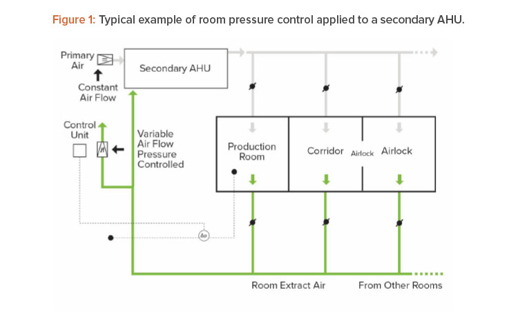
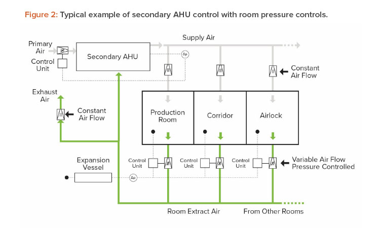
The control of AHUs has a direct impact on the performance of room pressurization controls. In primary/secondary systems (where outside air is provided by a dedicated unit), the control schemes outlined in the preceding section can be applied at the secondary AHU. See Figures 1 and 2 for examples of controls applied to secondary AHUs.
Flow controls should not be applied in series (i.e., room flow control should not be applied in series with AHU flow control). If flow controls are applied in series, the difference in measurement error between the two sets of readings can cause the systems to “fight” each other, with both elements continually hunting and driving a control response that influences the other. This effect is particularly pronounced if the two flow control loops are not programmed and tuned identically.
Providing room pressure controls at the AHU level and again at the room level is not a recommended practice; a simpler system will perform more reliably. AHU fans and primary air should be controlled on supply duct static pressure. If room pressure controls throttle (restrict) the amount of room extract that is returned to the AHU, this amount of air must be made up by primary air. Failing to do so will result in a cascading failure where loss of room pressure results in reduced airflow, which exacerbates the loss of room pressure, and so on.
PRESSURE DIFFERENTIAL MEASUREMENT
Pressure Cascade Specification
The regulatory objective for pressure differentials can be summarized as maintaining a differential of 10–15 Pa (across the airlock) between adjacent rooms with doors closed and maintaining the desired airflow direction between rooms with a door open. The ISPE Good Practice Guide: Heating, Ventilation, and Air Conditioning (HVAC) 3 suggests that a 5-Pa differential between rooms of the same classification is a minimum to be maintained for product/process separation. This suggests that a differential less than 5 Pa is not robust.
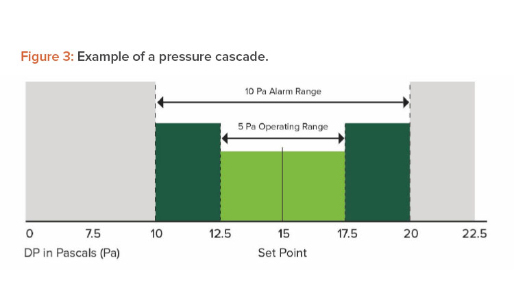
A pharmaceutical plant consists of many production rooms with various cleanliness classifications that must maintain differential pressures to ensure no cross-contamination between the areas. Figure 3 shows an example of a pressure cascade. The target is to provide a positive differential pressure from the cleanliness classification A to D, and from Grade D spaces to the adjacent controlled, not-classified, or nonproduction areas.
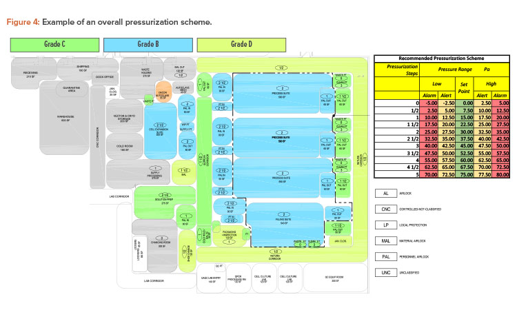
A well-designed and commissioned HVAC system should be able to limit room pressure fluctuations within a range of 2.5 ±Pa (the lighter green area in the middle of Figure 3); this is the operating range. If the room pressure deviates from the operating range, an alert (warning) should be issued to call for maintenance attention. If the room pressure deviates from the set point by 5 Pa or more for a predetermined period of time, an alarm should be activated (i.e., an action limit/alarm .) Figure 4 presents one possible operating pressure cascade between rooms with set points as well as alert and alarm points in half-step increments (nominally across each door of an airlock). Note that there is no requirement for an equal pressure drop across each door of the airlock. This cascade maintains 10 Pa between the upper and lower operating limits, from clean to the less-clean production rooms, even when both rooms are at the limits of their operating ranges (the lower-room-pressure room at the high end of the operating range and the higher-room-pressure room at the low end of the operating range). This setup also results in manageable velocities across any opening between Grade B and Grade D rooms (e.g., a “mousehole” for filled vials moving by conveyor from filling to inspection), and it ensures that some difference is present even when the rooms are in alarm. As an alternative to this approach, alerts and alarms may be generated based on calculated room-to-room pressure differentials between rooms of different classifications. In this case, the room-to-room (across the airlock, if any) pressure setpoint is normally around 15 Pa, with an alert at 12.5 Pa and the alarm at less than 10 Pa.
Airflows to Adjacent Rooms
To maintain room pressurization, air must be supplied to replace air flowing to adjacent rooms with lower pressurization. This “leakage” airflow goes through openings such as cracks around doors, piping penetrations, ceiling system cracks, and wall openings (e.g., “mouseholes” for vials moving from filling to inspection). These flows are important elements to account for in the HVAC system design.
To achieve design pressure differences, it is also important to maintain dropdown seals (where used) and door closers that are intended to ensure consistent operations. Often, door seals are not used. This is to simplify maintenance and to ensure that the leakage airflow is sufficient to be controlled. “Controlled leakage” from higher- to lower-pressure rooms is a means to maintain stable room pressure. It also supports the FDA requirement for outward airflow in the open-door situation 1. This is often done using the leakage through gaps around doors. Alternatively, when that leakage is insufficient to ensure a good outward flow with the door open, grilles, dampers, or pressure stabilizer dampers can be employed. In the latter approach, normal airflow is through the damper: When the door opens, the damper closes and the air flows through the door opening.
DIFFERENTIAL PRESSURE MEASUREMENT AND MONITORING SETUP
The differential pressure cascade within a classified area must be monitored to demonstrate that the pressure cascade is effective during manufacturing operations. When the differential pressure is across rooms with different classifications, monitoring of differential pressures across rooms with differing classifications is a GMP expectation 1.
The engineering system that supports maintenance of these differential pressures is a good engineering practice. There are two approaches: measuring room to room and measuring from each room to a common reference location.
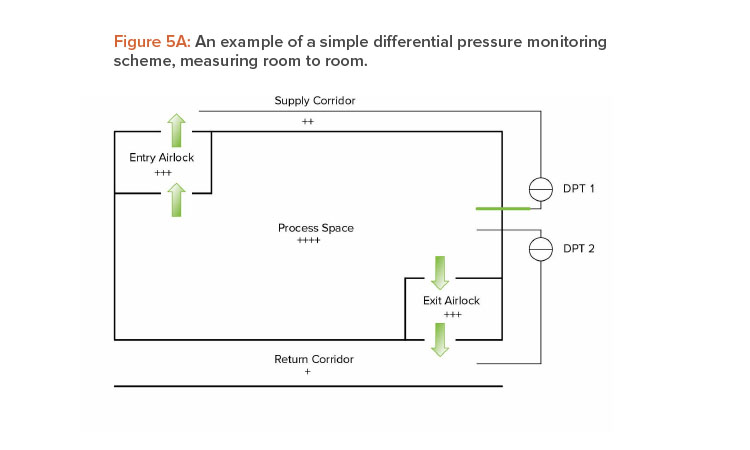
Measuring from Room to Room
This approach is easy to implement and does not require any calculation in the automation system (see Figure 5A). With a very large facility, depending on the layout, instrument accuracy, and alarm settings, using this approach would not provide visibility of any undesirable differential pressures between different suites. This design option may use fewer differential pressure transmitters and allows direct measurement of the individual room pressures, which can simplify control.
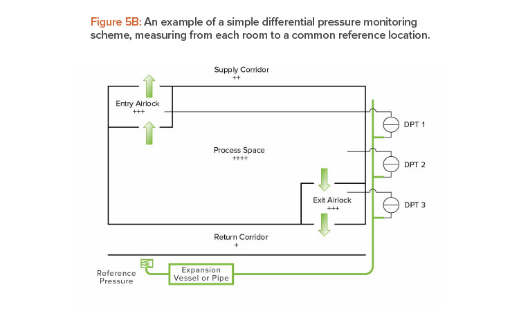
Measuring from Each Room to a Common Reference Location
This approach is often used for monitoring and/or control of complex facilities (see Figure 5B). In this scheme, all rooms are connected back to a common reference area. The area for the reference pressure should be inside the building (pressure neutral instead of pressure controlled). The room-to-room differential pressure values can then be calculated, with alarms based on the calculated values, as previously outlined. This system’s functionality is dependent upon the use of a stable reference point.
Measuring the Common Reference Pressure
A suggested design for measuring the common reference pressure is to:
- Plumb the low-pressure ports on all differential pressure transmitters into a common manifold.
- Connect the common manifold to an expansion vessel or large-diameter (3- to 4-inch) pipe. The expansion vessel or large-volume pipe manifold helps damp many transient air pressure fluctuations.
- Locate the reference point within the building, outside of the controlled pressure space and away from other unstable influences, if possible.
Using reference points within the unventilated or continuously fixed, ventilated interstitial space is an excellent and relevant choice for a stable reference. Outdoor references are rarely stable enough for responsive room pressure control.
INSTRUMENT SELECTION
Avoid large instrument ranges that extend significantly outside the range required. Similarly, select ranges of accuracy within the operating ranges of ±0.25 Pa. In deviation handling, information about whether the pressure was low or negative is relevant. Therefore, consider including part of the negative scale in the instrument range. For example, for a differential pressure that should be 50 Pa, an instrument range of -10–100 Pa could be used. Instruments should be robust enough to take the pressure fluctuations experienced in use and during calibration.
INSTRUMENT SIGNAL PROCESSING
It is desirable to see the actual differential pressure, which implies a fast-responding instrument, but it is also important to ensure stable control. Often, the control signal is filtered due to the extremely low pressures associated with space pressurization of the order of 2.5–50 Pa (0.01- to 0.20-inch water gauge). Signals from space pressurization instruments are often unstable, especially at the low end of the device’s range. Use of rolling average values or time-weighted rolling average values can be useful to help provide stable control and limit the appearance of nuisance alarms. At a minimum, a short time delay should be used.
ALARM DELAYS
Room pressurization, while a regulatory expectation for classified spaces, is not necessarily a primary or process parameter. Rather, it is important as an indication of a space’s ability to protect itself from airborne external contaminants. For this reason, loss of target room pressurization rarely needs to be reported immediately, as loss of pressurization is not necessarily indicative of a loss of clean conditions or incorrect airflow.
The delay prior to reporting pressurization alarms is commonly set to a few minutes (typically less than 10) and is supported with data on the duration of door opening needed to perform the process and study the impact of the maximum duration of pressure loss. These impact studies may include open-door particle counts, smoke studies of the ingress of air from lower-classification spaces to higher ones, recovery studies from upsets due to door opening, and similar qualification activities to ensure the maintenance of the desired classification when the door is open.
When establishing the alarm categorization, consider the potential impact of a reverse airflow (room differential pressure reversal or inversion). It is common to focus on internal differential pressure events; however, it is also important to consider external differential pressure events and the potential for ingress from outside spaces. A best practice is to observe the time associated with loss of conditions due to an HVAC system failure to assure that the pressurization alarm delay is set to a safe value before conditions (pressure differentials, particle counts, temperature humidity etc.) are lost. This can be arrived at by simulation or by reviewing historical operational data.
DOOR CONTROL
As noted in Table 1, the US FDA has explicitly stated that room pressurization must be maintained during periods when the door is closed, and door control when any single door to an airlock is open must therefore be strictly enforced 1. The difference in pressure between adjacent rooms of different classifications separated by an airlock should not change even with door opening, as one door is always closed; however, short-term variation may be observed. Loss of pressure between differently classified spaces is indicative of an HVAC failure, not a door control failure.
Pressurization alarms are typically used to report changes in pressure due to door openings, not to report HVAC system failure. Depending on the system, they may also provide an alarm if the HVAC system fails. Because brief door openings are common, alarm delays are required to discriminate excessive door-open time from common and allowable door openings. It should be noted that door switches could also be used to determine the state of doors, monitor door-open times, and confirm closing.
The best practice is to observe the necessary door-open time associated with operations and ensure that the door-open alarm delay is set to a value greater than the maximum necessary door-open time. This setting can be determined by simulation or by observing operational data. It should be less than the time associated with loss of conditions.
POWER FAILURE RESPONSE
In areas where the power supply is unreliable and there is no standby generation, the environmental monitoring system should be on an uninterruptible power supply so that there is data to cover the duration of the event. If power loss is a risk, standby power (depending on the process and materials, consider an uninterruptible power supply [UPS]) should be provided to biosafety level 3 and biosafety level 4 equipment, Grade A unidirectional flow zones, isolators/restricted access barrier systems, and, ideally, Grade B areas.
The HVAC design should consider the power failure risk and controls—for example, one consideration could be the use of shutoff dampers to ensure that air movement is controlled. This aspect of the proposed HVAC design should be assessed during design qualification to ensure that it is robust. A risk assessment should be used to support the specific installation and determine the potential risks that could be caused through loss of differential pressure (part of the CCS).
Operational verification should include confirmation of system function and control loop tuning, as well as simulation of potential failure modes and system restarts. It should also address expected operational issues such as opening both doors to an airlock. Environmental qualification should include verification of the temperature, relative humidity, airborne particle levels, and airborne microbial cleanliness. In practice, there is usually a loss of pressure for a short time during a line clearance and minor clean that may be within acceptable limits prior to returning the area to operation. This could span the time from when protection is not lost (seconds to a minute) to when protection is lost but conditions are maintained. A time should be established after which the line must be broken down and a 3x-clean initiated. A safety factor is always applied to any test results. For example, a study yielding good results for about 45 minutes may use a safety factor of 3 and set the 3x-clean requirement to 15 minutes.
If a power failure event is considered unlikely, a strategy should be defined in case the event does occur. For example, the strategy might involve taking additional environmental monitoring samples, recording personnel flow in the area during the event, and noting observations about outside conditions, which part of the higher-classified room was impacted by pressure inversion, and whether unidirectional flow countered any ingress.
CONCLUSION
Though regulators have clearly defined expectations for differential pressures, there are numerous ways to approach the design, monitoring, and alarming of differential pressures areas. This article discusses options for HVAC systems, the control of AHUs, and other aseptic manufacturing concerns for differential pressures to ensure best practice is used. The use of best practice will help prevent cleanroom contamination and reduce the risk of contamination.


