Supporting Cell & Gene Therapy through Multimodal & Flexible Facilities

Cell and gene therapies (C>) have unique needs in manufacturing suites that differ from those for classic product biopharmaceuticals. Facilities must be created with flexibility in mind, able to run multiple products and production types to remain viable.
Cell and gene therapies are part of advanced therapy medicinal products (ATMPs) and offer great potential for regenerative medicine, including ways to treat and cure a variety of acquired and inherited diseases. C sponsors currently address numerous emerging pharmaceutical entities, as well as manufacturing platforms, modes, and scale. This can require special manufacturing considerations less common in well-established biopharmaceuticals, such as enzymes or monoclonal antibodies (mAbs).
These considerations include processing safety (e.g., levels of biological, chemical, and solvent handling safety), multiple scaled-out batches, and the requirement for end-to-end aseptic processing. C> is still a relatively young field and therefore continually evolving, which has resulted in diverse research pipelines, entity types, manufacturing technologies, clinical trials, and commercial scale facility designs. For all these reasons, C> have unique needs or require special considerations in manufacturing suites beyond those for classic products. This article discusses types of facilities and design considerations for C>.
Flexible Facilities
In many C> processes, success is dependent on the ability to efficiently deliver new genetic material to the target cells. This can be challenging for many reasons: it can be difficult to estimate the size and number of polynucleotides to transfer, the efficiency of the vector in the particular cells addressed, the scale of production required, and whether a patient’s immune system will respond to vector particles as a microorganism. For such reasons, a number of viral vector (VV) systems are currently in place, with many other gene-vector systems in development.
| Viral Vector Modality | Percentage of Worldwide Assets (%) |
|---|---|
| Adenovirus | 5 |
| Adeno-associated virus | 82 |
| Lentivirus | 10 |
| Other | 3 |
| Viral Vector Modality | Number of Clinical Trials |
Percentage of Total in Use (%) |
|---|---|---|
| Adenovirus | 575 | 50 |
| Adeno-associated virus | 315 | 28 |
| Lentivirus | 250 | 22 |
- 1Capra, E., A. Godfrey, A. Loche, and J. Smith. “Gene-Therapy Innovation: Unlocking the Promise of Viral Vectors.” McKinsey & Company website. Published 17 May 2021. https://www.mckinsey.com/industries/life-sciences/our-insights/gene-therapy-innovation-unlocking-the-promise-of-viral-vectors
- 2Bulcha, J. T., Y. Wang, H. Ma, P. W. L. Tai, and G. Gao. “Viral Vector Platforms Within the Gene Therapy Landscape.” Signal Transduction and Targeted Therapy 6, no. 53 (2021): doi:10.1038/s41392-021-00487-6
This diverse landscape and process-specific supply-chain issues are driving the need for highly flexible facilities that may run multiple products and/or production modes. The traditional, rigid facility design approach associated with the well-defined processes of classic products are not meeting the needs of the C> manufacturing field. Tables 1 and 2 exemplify an aspect of this diversity in only the most popular current VV methods. Each vector modality presents distinct values in the current range of therapeutic entities, clinical indications, cells to be modified, and evolving manufacturing methods. The most successful vectors to date have been adeno-associated virus (AAV), adenovirus (AdV), and lentivirus (LV). AAV vectors are commonly associated with in-vivo gene therapies; AdV vectors show promise for vaccine applications including oncolytic virotherapy; and LV vectors are commonly associated with such ex-vivo approaches as CAR-T cell therapy.
The two sources cited for Tables 1 and 2, while contemporary to each other, show a slightly contrasting view of the current VV landscape. This highlights yet another of the challenges for sponsors of new C> products: The facility and suite design must be flexible to support many existing future unknowns, including the following:
- Particular products successfully licensed
- Number and type of processes validated
- At-scale manufacturing operations and flow
- Timeframe of launch and capacity demand
Multimodal Facilities
The requirements for a multimodal facility can be complex and variable. They depend on such factors as the particular focus of the manufacturing company and whether that company is an owner-manufacturer or a contract manufacturing organization (CMO). Multimodal C> facility designs are outlined next, followed by an overview of flexible facility design criteria.
CAR-T Manufacturing Facility
Although there is significant and exciting progress in a variety of cellular therapy designs, all those currently approved for commercial production involve autologous (cells from the patient) CAR-T cells. Autologous therapies are effective, but present significant limitations in sample logistics, manufacturing facility throughput capability, and variability in the performance of cell samples from different patients. Allogeneic therapies (employing a master cell bank from donor cells) offer the greatest potential for a scalable, off-the-shelf solution, provided that the risk of identified complications can be overcome.
Although there are many advances in cell isolation, activation, transduction, and expansion technologies, currently popular autologous approaches demand a significant footprint for the manufacturing facility. Production of ~3,000 patient batches per year using in excess of 100 pieces of specialist equipment requires a facility of ~4,500 m² for an autologous therapy.3 In comparison, Allogene Therapeutics, for example, has indicated that their lead candidate for an allogeneic therapy (ALLO-501A) may produce up to 20,000 patient doses annually for a fraction of the equipment and manufacturing batches required for an autologous equivalent.4
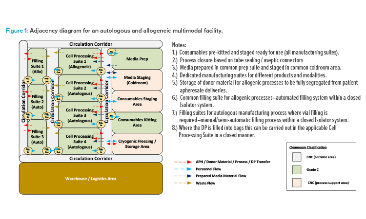
This potential inspires many CMOs and owner-manufacturers with multiple candidates in clinical trials to maximize the potentials for their facility by engineering the ability to manufacture either autologous or allogenic therapies, or both in parallel. The current basis for design requires all individual therapies (each having a distinct gene vector component) to be manufactured in dedicated suites. To reduce risk of product cross-contamination and protect chain-of-identity requirements, suites associated with autologous operations also require segregation from allogeneic operations. However, support functions such as consumables kitting and media preparation can be shared across such multimodal facilities.
The adjacency diagram in Figure 1 illustrates one potential layout approach for this type of facility. Unidirectional personnel flow should be maintained through the BSL-2 (or higher) spaces to ensure containment of the suite through a bubble/sink arrangement on (personnel airlock) PAL-In/PAL-Out. Product and waste flows should be separated with dedicated transfer routes to prevent risk of cross-contamination. However, dedicated supply and return corridors are not required. The circulation corridors can be designated as bidirectional common spaces, provided that procedural controls are in place to ensure that all in-process product and biohazardous waste materials are properly contained before transfer.
- 3 Judd, S. DPS project experience, December 2011–August 2022.
- 4Stanton, D. “CAR-T Approvals Marred by Autologous Manufacturing Limitations, says Allogene.” BioProcess Insider website. Published 13 May 2022. https://bioprocessintl.com/bioprocess-insider/therapeutic-class/car-t-approvals-marred-by-autologous-manufacturing-limitations-says-allogene/
![Figure 2: Development of a stable producer line for lentivirus production. (Source: Eureka Biotechnology [6]. Reprinted with permission.)](/sites/default/files/2022-10/1122_PE_ND_CoverStory2_03.jpg)
(Source: Eureka Biotechnology.6 Reprinted with permission.)
Viral Vector Manufacturing Facility
Both CMOs and owner-manufacturers with different production modality candidates under consideration require maximal flexibility to facilitate manufacturing of the different modalities without the need for expensive and continued facility modifications. Although there are a number of new gene transfer technologies in development, current factors in flexible facility design requirements for VV manufacturing include the following:
- Production batch strategy: Will the facility operate on a campaign basis with only one product manufactured at a time, or will different products be manufactured in parallel?
- Production modalities: Will there be distinct, unique production processes and equipment employed either sequentially or concurrently?
- Host cell line requirements: Will the manufacturing processes all be based on mammalian cell lines or will insect cell lines also be employed?
- Cell culture mode: What are the requirements for adherent, suspension, and/or continuous culture?
- Method of production: Will the manufacturing operations support the popular transient transfection (TT), the newer stable producer lines (SPL), or both?
- Yield vs demand vs capacity: Will the culture volumes and bioreactor style be similar or divergent between products/modalities?
If manufacturing will operate on a campaign basis, then many aspects of facility design can potentially be comparable to those of a single product facility, with a rigorous changeover protocol required to sanitize manufacturing areas. If the manufacturing operations are to include both insect and mammalian cell lines, and it is only feasible for the company to construct a single manufacturing train, then such a campaign-based approach is required.
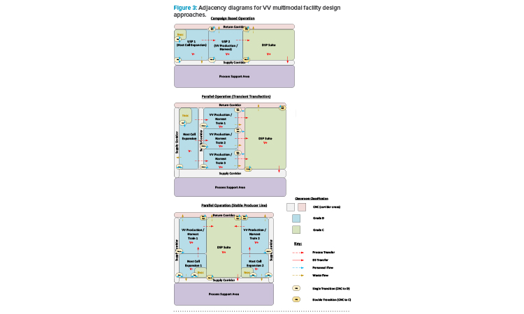
If manufacturing with different modalities is to occur concurrently, in parallel, then segregation requirements will depend on whether the approach to viral production follows a TT or SPL approach. Figure 2 depicts the process development roadmap associated with an SPL. It is a regulatory requirement that different VV types are manufactured in segregated manufacturing suites.5 The TT approach requires introduction of plasmids to the N-stage production bioreactor to produce the loaded viral particle. For an SPL, the vector and transgene instructions are integrated into the host cell genome, allowing induction of the complete viral product once the required host cell density has been achieved.
With the TT approach, where different products employ a similar host cell line, it is possible to operate the host cell expansion train as far as the N-1 stage in a ballroom area, with multiple batches being manufactured in the same manufacturing suite in parallel on the basis of closed processing. The product-specific aspect is introduced at the N-stage bioreactor step through the addition of the plasmid cocktail. Segregation of the manufacturing suites from this step forward is required for parallel manufacturing of the different products. With an SPL, as both the vector instructions and new genetic material are already present in the host cell seed stock, end-to-end segregation of the manufacturing process is required for the parallel manufacturing of different products.
Another factor to be considered is the design of downstream processing (DSP) suites and spaces. Maximizing the throughput of a multi-train upstream processing (USP) area will likely result in the USP trains operated in a staggered fashion. The DSP operations here often take between four and seven days and, if the Takt (cycle) time associated with the USP operations is greater than this, then only one DSP train will be required to ensure full “temporal segregation” between batches. A rigorous changeover protocol will then be required to sanitize the DSP area before processing of the next batch. However, the most flexible and streamlined design of the DSP area is to have the full DSP train in a single ballroom suite. This approach can be facilitated by ensuring that, through one of a variety of means, fully closed process operations are maintained throughout the DSP train.
An additional factor to consider is adventitious virus safety; closed processing will guard against the potential ingress of other product- or process-related agents. This is an important factor in many cases because, due to the size of the viral particle, only an AAV process can include a virus filtration step. Therefore, if a multi-vector mode facility will potentially be manufacturing AAV in a process that includes a virus filtration step, it may not be practical to segregate the pre-viral and post-viral areas.
The risk mitigation measures here therefore need to be designed into the manufacturing operations, and not based upon their physical segregation. Figure 3 presents a series of adjacency diagrams that depict the potential approach to multimodal facility design based on the preceding discussion.
Viral and Non-Viral Modalities Facility
Critical preprocessed ingredients associated with C> manufacturing operations, such as plasmids for TT processes and LV for CAR-T cell therapies, can present supply-chain issues if provided by third-party vendors.
One approach to protecting the integrity of this supply chain is to bring the operations for these key modalities in-house. For example, if the therapeutic product is a CAR-T cell therapy based on a TT modality, then having a facility supporting plasmid and lentivirus vector manufacturing, as well as the cell therapy process, would provide significant advantages.
Such a facility would require three defined and fully segregated manufacturing areas: plasmid manufacturing is E. coli, microbial fermentation based; LV vector manufacturing is animal cell, virally positive based; and autologous cell therapy (CT) processes involve blood product directly from the clinical patient. Designs ensuring the lowest risk of cross contamination between these different manufacturing areas are essential, and achievable, provided there is sufficient space associated with the new facility.
The approach to segregating the different areas may be through either vertical or horizontal integration. Having a vertically integrated facility, with the different manufacturing areas on different floors, has the advantage of requiring a smaller overall footprint, which can be beneficial if the site boundary area is limited. A horizontally integrated facility, with all manufacturing on the same floor, can potentially optimize the material, product, and waste flows.
- 6Xue, B., N. Yang, A. Liu, B. Liu, J. Liu, and A. Lin. “The EuLV System, an Inducible Stable Producer Cell Line for Lentiviral Vector Production.” Cell & Gene Therapy Insights 8, no. 2 (2022): 199-209. doi:10.18609/cgti.2022.022
- 5European Commission. “EudraLex Volume 4–Good Manufacturing Practice (GMP) Guidelines.” EudraLex. Accessed 11 August 2022. https://health.ec.europa.eu/medicinal-products/eudralex/eudralex-volume-4_en#part-iv---gmp-requirements-for-advanced-therapy-medicinal-products
Flexible Facility Design Considerations
Demands for flexibility derive from requirements to support diverse or emerging therapeutic entities, processing modalities, equipment design, security of supply, and manufacturing scales. Some key factors associated with the design of such a flexible facility include:
- Suite design for multiple process train support
- Suite design for modular and smart automation7
- Equipment capable of multiple, diverse applications
- Manufacturing train design for ease of modification and changeover
- Minimization of cleanroom grading, supporting ease of operation, divergent closed operations, and streamlined activities when relocating equipment
- Facility design to support compliance of the most stringent biological, chemical, and solvent handling safety requirements of the modalities envisioned
Beyond facility design and process flows, C> production equipment is becoming commercially available to support the development of multimodal and flexible facilities. Both systems and equipment are emerging to support modularity of operations; ballroom application; and ease of scale-up/down and scale-out/in. Respective equipment is engineered with sample number, production volumes, flow rates, and/or turndown ratios to enable variability in capacity.
Single-Use Technology
Single-use technology (SUT) is typically used across C> facilities, and it offers many advantages that support process/product flexibility. These advantages include inherent process closure, as well as reduced cross-contamination risk, suite classification, service requirements, and time in changeover.
Product contact components associated with SUT are disposed of after use, eliminating the requirement for the cleaning and sterilization of equipment, as well as for related validation studies. SUT facilitates fully closed process operations using aseptic connectors, tube welding, and aseptic dis-connect methods (i.e., tube sealing or crimping). Fully closed operations enable the downgrading of cleanroom classifications, concurrent disparate manufacturing processes, and streamlined equipment move in/move out activities.
Unidirectional personnel, in-process product, and waste flows are required for the V+ (BSL-2 or greater) areas, illustrated in Figure 3. Transfers between single-use systems (SUS) require specific suite adjacencies compared to stainless steel facilities, where hard piped transfer lines can potentially be run indefinitely across a facility. These unidirectional flow demands, combined with SUS suite adjacency requirements, can add complexity to facility layouts when considering how transfer tubes need to run between suites, particularly where multiple USP suites all feed into a single DSP suite. Ideally, a transfer tube should run through the wall between directly adjacent suites. Where this is not possible, the transfer tubes can potentially be brought at a high level over short distances through a transition corridor, with isolatable tubing pass-throughs installed in each cleanroom wall.
Emerging Standards and Equipment
Emerging standards in design elements, such as physical connectors and service specifications, are occurring in such areas as data transmission and curation that support process-related analytics, equipment maintenance, and process monitoring and control. Although more can certainly be done, a growing number of equipment and instrumentation specifications can be vendor agnostic. Intra-vendor plug-and-play equipment connectivity is currently available for some processes, and there is less need for customization of some assets.
Equipment is being designed to support flexibility in the scale-out or reconfiguration of a process. Individual components, skids, and modules can be added, removed, or rearranged with minimal customization. These equipment design elements also allow a system to operate in a different geographic setting or service conditions than its initial establishment and validation. Especially when employed in the growing number of podular suites, this promotes ease of the worldwide transport of such processes.
Utility Panel Design and Optimization
Partially automated SUT-based equipment is “plug-and-play” and relatively straightforward to move in and out of a manufacturing suite as equipment train modifications are required. Ease of equipment changeout without the need for suite modifications is supported by the design and set-out of utility panels (UPs) and access supporting such equipment.
UPs provide the services required to operate relevant SUT and semi-automated equipment, including power, data connections, process control systems (PCS), process gas supplies, jacket service connections, and liquid waste connections. UPs can be wall- or ceiling-mounted. Example determining factors for UP location are that ceiling-mounted panels allow flexibility in the equipment layout without the need for long, trailing cables, but equipment requiring drain connections should be associated with a wall panel. Key features maximizing the flexibility of the UPs include maintaining a common design approach, and ensuring that the process automation design associated with such equipment as customized SUT cell-processing carts and mixers is related to the UPs, as opposed to the individual equipment.
Common design approach:
- Avoid unique UPs designed specifically for an individual piece of equipment
- Limit the number of different UP types, and select the most appropriate type for each manufacturing area/operation
- Accept that the full range of services associated with each type of panel need not be required for each piece of equipment potentially connected
Relate PCS connections to the UP:
- Process automation is associated with the UP, not the equipment connected to it (standardized instrument transmitter connections at each UP)
- Single-use mixers (SUMs) and custom-designed process carts will bring the instrument connections to the UP with a heavy duty, plug-and-play electrical connector
- The specific SUM or cart will be recognized by the PCS through an automated signal or scanning of a quick response (QR) code on the equipment frame
- Different SUMs and carts will have different instrument requirements and the PCS will recognize the equipment currently connected
A thorough assessment is required to determine the necessary level of flexibility across the manufacturing area. The number of services associated with each panel are factors in their size and cost, and there should be a trade-off between the maximum possible level of flexibility and what is sensibly required.
Cleanroom Grading Approaches
Early commercial-scale C> facilities favored a conservative approach to cleanroom grading, whereas processes that involve open handling of sterile operations are now commonly performed in a biosafety cabinet (BSC). Grade B cleanrooms are therefore relatively commonplace, yet these tend to limit flexibility due to the constraints around maintaining the associated stringent environmental controls. Operating a C> facility, such as a VV manufacturing facility, with Grade C or potentially even Grade D manufacturing suites is a viable option when using SUT (and closed-process operations), as described above and highlighted in Figure 3.
For the smaller-scale cell therapy operations, the transition away from the use of BSCs in Grade B suites can be achieved using isolator technology, such as custom isolator systems designed around the specific process. These may include cell culture operations such as cell factories and incubators, or filling operations carried out using automated and semi-automated systems. The ergonomics of the isolator systems can be optimized through effective selection of the glove material, with thinner and more flexible materials now available for undertaking the delicate tubing manipulations associated with CT processes.
An isolator can be categorized as providing full aseptic segregation of the operations inside the unit, reducing the required environment classification, as compared to operating a BSC. Isolator technology can facilitate different products or platforms being operated in the same area in parallel by installing multiple isolators in a single ballroom suite, potentially operated as a Grade D environment. This approach will maximize the flexibility of the area by minimizing the operational footprint from walls and airlocks.
A recent industry survey conducted on the C> marketplace indicates that only around 25% of CT companies currently operate Grade C cleanrooms with such closed-process operations.8 However, based upon the continually advancing manufacturing technologies, it is expected that there will be a significant shift toward reduced suite classification in the future.
Biosafety Design Considerations
Biosafety plays another key role in the design of a multimodal facility. As mentioned, designs must comply with the most stringent biosafety product and production requirements anticipated. Furthermore, geographic regions and internal company standards impose different biosafety requirements. Corporate strategies have often been based upon the regulations of the most stringent region that the company operates in, regardless of where a particular facility is located.
Examples of regional differences:
- The BSL associated with genetically modified HEK293 (or equivalent) cell lines used in TT processes are classified as BSL-1 in the EU and BSL-2 in the US.
- Third-generation lentiviral vector systems have recently been downgraded to BSL-1 (ML-I) in the Netherlands, but remain a BSL-2 material in other regions.9
One common approach is to use the classification BSL-2+, which is a risk-based approach that implements certain BSL-3 requirements above a BSL-2 baseline. As the majority of C> modalities fall within the BSL-2 category, BSL-2+ provides a robust strategy to ensure the facility will be suitable for a wide range of modalities. The nature of VVs puts them among the more biohazardous materials in C> operations, and a guideline for their BSL classification is outlined in Table 3.
| Viral Vector Type |
BSL | Comments |
|---|---|---|
| AAV | BSL-1 | Based on the use of a helper plasmid |
| AAV | BSL-2 | Based on the use of a helper virus |
| AdV | BSL-2 | Replication incompetent systems reduce risk, but are more challenging to process |
| LV | BSL-2 / 2+ | Recently reduced in the Netherlands |
| Retrovirus | BSL-2 / 2+ | |
| HSV-1 | BSL-2 |
To ensure containment of the suites to surrounding corridors, either recirculation or once-through air design can be considered in heating, ventilation, and air conditioning (HVAC) associated with higher biosafety levels. A recirculation approach requires an individual air handling unit (AHU) per manufacturing suite and may increase cross-contamination risk for multi-product/modality operations. A once-through air design can facilitate a single, larger AHU supplying multiple manufacturing suites, but may increase the utility demand compared to the recirculation approach.
High-efficiency particulate air (HEPA) filtration on the exhaust air from a facility is not typically included with lower BSL or non-biohazardous operations. The risk of exhausting biohazardous material via the exhaust air from a facility supporting closed process operations is negligible. It therefore follows that HEPA filtration is not required for the exhaust air on such a room or facility.
Product or equipment changeover for a manufacturing suite should be a repeatable and validatable process. Suitable methods include a vaporized hydrogen peroxide (VHP) fumigation of the suite. VHP can be supplied by mobile generators within the suite itself, or introduced to the suite via an inlet point in the supply ductwork. Either approach necessitates full isolation of the manufacturing suite from the surrounding area. This is achieved using such measures as isolation dampers on ductwork and interlocked airlock doors with gas tight seals to isolate the VHP vapors. VHP fumigation of a suite is an example of a BSL-3 requirement that may be implemented as part of a BSL-2+ strategy.
Waste Handling Considerations
Single-use consumables used in the main manufacturing operations of any C> process require handling as biohazardous waste following the BSL classification of the particular process. Decontamination / disposal methods vary, and they can have significant implications for the facility design and operation. The principal method employed is through the use of an onsite decontamination autoclave. These units can be large and have significant utility demands and lengthy cycle times, but the waste can be subsequently disposed of as inert plastic waste.
An alternative is to transfer the functional responsibility for decontamination and disposal to a specialist waste management contractor. Factors affecting the choice of approach include consideration of the legal or regulatory responsibilities, decontamination of reusable gowning materials, the volume of waste being handled, and the available frequency of collection by the contractor. If genetically modified organisms containing biohazardous materials require prolonged storage before collection, a temperature-controlled waste staging area is likely to be required.
If onsite decontamination is employed, the location of the required facilities can impact the flexibility of the site. Lower BSL ratings (BSL-1) indicate the decontamination facilities must be available somewhere at the production site. More stringent guidelines (BSL-3, and potentially BSL-2+) state that the decontamination facilities are at the boundary of the specific BSL zone. How the specific BSL zones are defined, e.g., whether there are multiple segregated manufacturing areas in the same facility, can dictate where the decontamination facilities should be installed to promote flexibility. Examples of this include facilities for the manufacture of both viral and non-viral modalities, and how a facility is operated with respect to the common support areas and circulation spaces.
Installation of a decontamination autoclave at the boundary of a specific manufacturing area, as opposed to installing in a common waste area, can increase flexibility. This approach provides robust protection against cross-contamination in other areas of the facility, but potentially necessitates additional decontamination autoclaves, increasing cost and spatial considerations. An alternative approach involves detailed procedures ensuring robust waste material containment before transport to a common area. The most suitable approach should be determined through a structured risk assessment during the facility design phase.
For a facility that includes multiple defined manufacturing areas, careful consideration is required in the design of liquid waste systems. Either separate biowaste waste systems must be provided for each area, or the piping design needs to guarantee no possibility of backflow or crossflow between waste headers from different areas. If a common waste system is desired, then separate headers should be run from each area that connect independently into the waste collection tank/treatment system.
Process Modeling and 3-D Design
Effective upfront planning is required to ensure optimal flexibility in a multimodal facility. Detailed process and structural models allow comparison of different manufacturing scenarios to determine the optimal approach for a particular site, while not limiting manufacturing capabilities or incurring excessive costs.
Process modeling software allows different processes to be built out and then scheduled in campaign or parallel manufacturing scenarios. This supports optimization of specific throughput requirements following each stipulated design constraint and priority rank. Such software can be used to not only model the known processes associated with the facility, but also to run theoretical scenarios to plan for potential or yet unknown future products. The outputs from these models will determine equipment requirements, identify bottlenecks, and “right size” utility and waste systems. Facility and equipment layout designs that support existing needs and outputs from theoretical scenarios guide proper sizing and spatial planning of manufacturing suites and support future changeout or expansion.
Advances in process modeling and building information management software now allow development of a true digital twin of a facility to be developed. Discrete event simulation (DES) software can model the suites and process flow of manufacturing operations as sequences of events over time. This provides an accurate picture of the equipment requirements and of how all the manufacturing and ancillary operations fit together to produce the desired throughputs and other goals for a facility. This is particularly powerful for more labor-intensive processes such as CT modalities. Planning the movement of operators through the facility brings significant benefit to spatial planning of both the manufacturing suites as well as such ancillary areas as airlocks, main gowning areas, and locker rooms.
When it comes to the design of the facility itself, this is almost exclusively now done using three dimensional (3-D) modeling software tools. Different engineering disciplines, such as architectural and process piping, may use different software packages, which can then be combined into a single coordinated model. The end result is a 3-D model of the facility in which people can “walk around” to get a feel for how each area will look and adjust spatial arrangements to optimize ergonomics. The output from the DES software is an animated model that uses 3-D objects to illustrate the orientation and placement of manufacturing and support equipment, as well as to show how the operators will interact and undertake their activities. The 3-D objects used in the model can be customized to show a true representation of the specific equipment and an actual 3-D model of the building can be imported into the DES model. The consequent amalgamated in silico model (a digital twin) then provides a precise virtual depiction of how the facility will both appear and operate. This very powerful tool can show how the introduction of different equipment, manufacturing modalities, and processes will affect requirements of the facility compared to the start-up conditions and enable companies to plan accordingly.
Digital Biomanufacturing
Finally, such comprehensive digital initiatives as Industry 4.0 are now making serious inroads to biopharmaceutical manufacturing. The digitalization of biomanufacturing is supporting flexibility in multiple product/process facilities. Structured, segregated, and distributed modeling of cell cultures and the hybrid (mechanistic and data-driven) model-based control of bioproduction is enabled by advances in culture omics, process analytics, and data science. Edge computing, the Internet of Things (IoT), and machine learning (ML)-supported digital twins are advancing capabilities in plant maintenance and system control, procurement, process scheduling, prediction and control, and changeover ease.
- 7Langhauser, K. “Positives, Negatives and Mixed Results From This Year’s Survey.” Pharma Manufacturing website. Published 21 September 2021. https://www.pharmamanufacturing.com/articles/2021/smart-pharma-survey-results-pharmas-digital-prowess-put-to-the/
- 8CRB.“2020 Cell and Gene Therapy Report.” CRB Horizons Reports website. Accessed 11 August 2021. https://go.crbgroup.com/2020-horizons-atmp
- 9GMO. “Important Changes to the GMO Regulation as of 1 October 2021.” GMO Office website. Published 4 October 2021. https://ggo-vergunningverlening.nl/nieuws/belangrijke-wijzigingen-in-regeling-ggo-per-1-oktober-2021
- 10Adgene. “Biosafety Resource Guide.” Adgene website. Accessed 11 August 2022. https://www.addgene.org/biosafety/?gclid=EAIaIQobChMInILMkbTT-AIVCb_tCh3S7AZlEAAYASAAEgIvYfD_BwE